myCNC-ET6
- 5 years ago.
ET6 Top View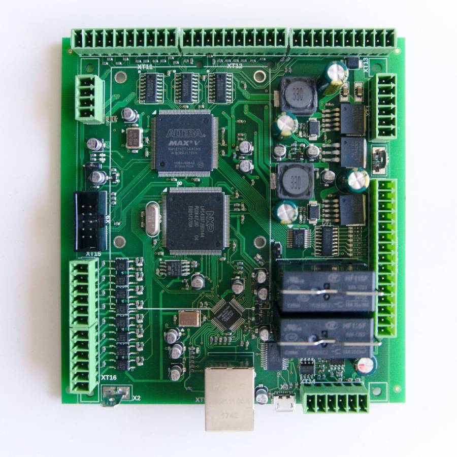
myCNC-ET6 controller specifications:
| Number of motor outputs |
6 |
| Motor driver outputs |
pulse-dir, |
| Maximum pulse frequency |
3 MHz |
| Binary inputs |
8x galvanic isolation, |
| Binary outputs |
2 relay outputs 2 open collector outputs |
| PWM outputs |
3x - open collector |
| RS485/RS422 |
1x RS485 with Modbus ASCII/RTU implementation |
| Computer connections |
Ethernet (PC/ARM, Linux, MS Windows) |
Power supply connection
24V DC is used to supply myCNC-ET6 control board. Power consumption depends on the external peripherals you have connected to the open collector outputs and +12V/+5V outputs. Normally. the 24V/2A power supply should be enough to power up the controller based kit with single board computer and 15'6" TFT screen. However, step-down converters on the ET6 board consume start current of about 1.5A and the 24V/1A power supply might be not enough to supply a single ET6 board.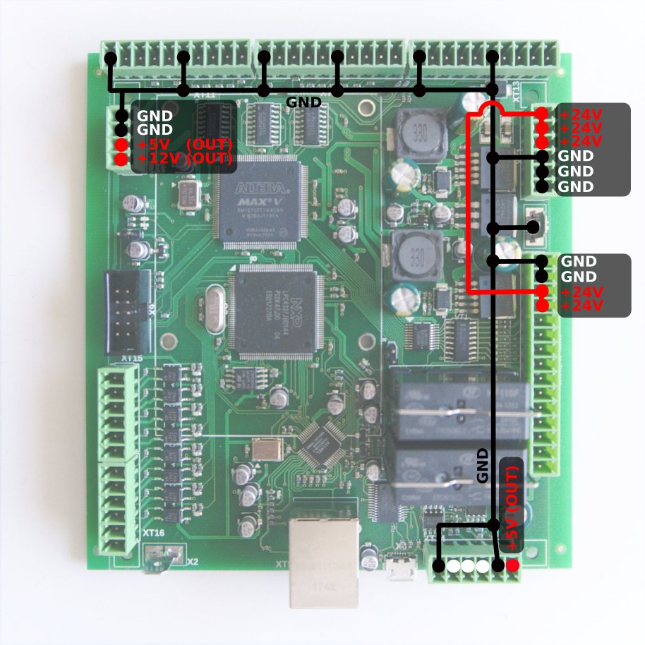
Pulse-Dir outputs
ET6 has 6 channel pulse/dir outputs, with a max pulse frequency of 3MHz.
ET6 pulse-dir outputs conform to the RS422 standard and are compatible with most of the servo and stepper drivers (line driver with paraphase signals of positive and negative polarity). Internal schematic for pulse-dir is shown in the picture below: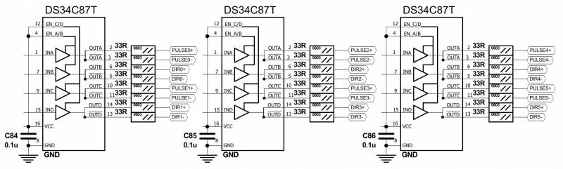
The pulse-dir connectors pinout is shown below: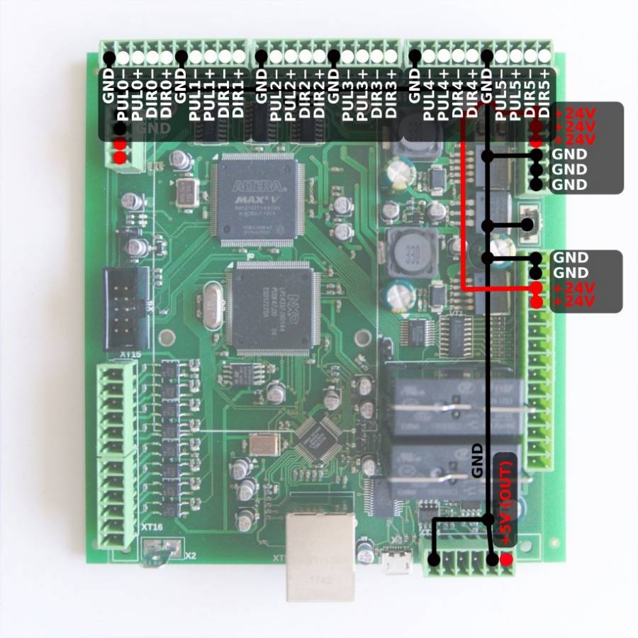
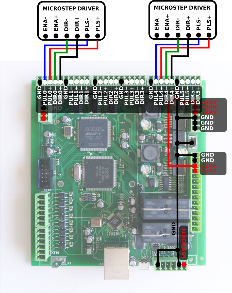
ET6 Output pins
ET6 board contains 7 output pins:
- 2 relay outputs (OUT#0, OUT#1)
- 2 open collector outputs (OUT#2, OUT#3)
- 3 PWM outputs (PWM#1, PWM#2, PWM#3)
| WARNING: ET6 board rev.1 has Output pin names printed on the Bottom side of the board. These names are NOT correct and differ from actual output addresses. Please check the table below to find out actual output addresses. |
| SILK prin | Actual Output Pin Address |
| OUT0 | OUT2 |
| OUT1 | OUT3 |
| OUT2 | PWM1 |
| OUT3 | PWM2 |
| OUT4 | PWM3 |
| P2A | OUT0 (A) |
| P2B | OUT0 (B) |
| P2C | OUT0 (C) |
| P1A | OUT1 (A) |
| P1B | OUT1 (B) |
| P1C | OUT1 (C) |
A schematic for the ET6 outputs is shown below: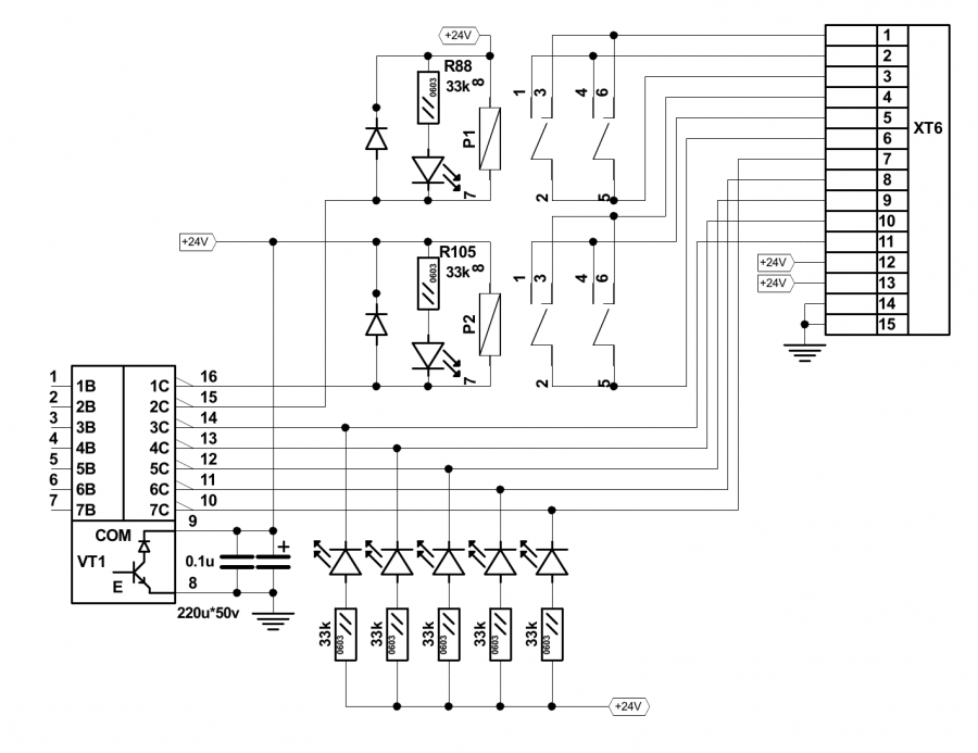
Connector pinouts for ET6 output pins are shown in the picture below: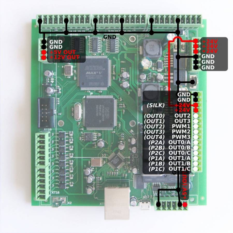
Galvanic isolated inputs
ET6 control board has 8 galvanic isolated binary inputs, 2 groups of 4 inputs each. Each group has separate power supply pins so inputs can be powered from different power sources. Using PNP and NPN sensors simultaneously if possible too.
Schematic for ET6 inputs is shown below: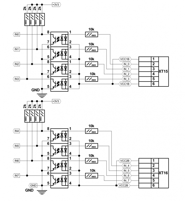
Connector pinouts for the ET6 galvanic isolated inputs are shown in the picture below: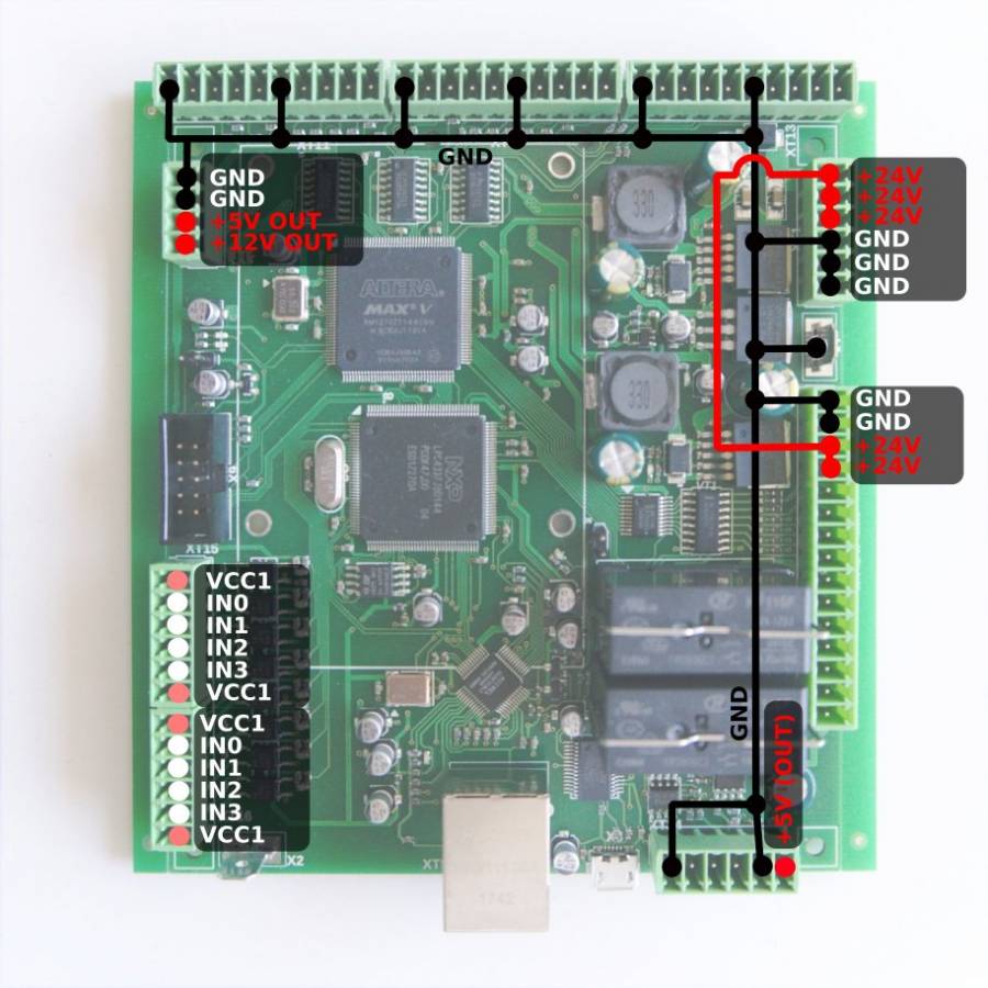
RS422/RS485 Bus
myCNC-ET6 control board has a RS485 bus connector. Modbus ASCII/RTU and Hypertherm Serial communication interfaces are implemented in myCNC-ET6 control board.
RS485 bus schematic is shown below: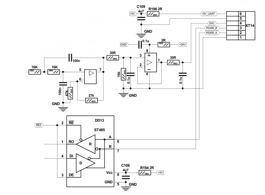
RS485 connector pinout shown below:
DAC output
myCNC-ET6 control board has DAC output for spindle speed control. DAC output range is 1 to 15V. The actual Max DAC voltage (ie 10V, 5V, 6V) can be set up in the myCNC control software.
Schematic design for the DAC output is shown below: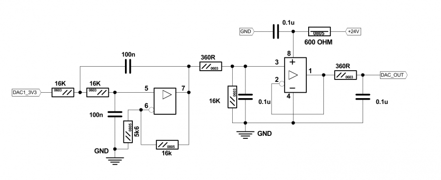
Connector pinout for the DAC output: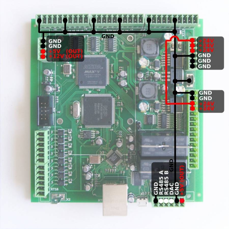
Connection Examples
3-wire NPN sensor connection example (external power supply)

3-wire PNP sensor connection example (external power supply)

3-wire NPN sensor connection example (internal power supply)

3-wire PNP sensor connection example (internal power supply)

Depending on the particular sensor, power can be supplied through any of the power input connections (5V, 12V, 24V). 24V was chosen in these examples as it is the industry standard.
Spindle speed control through DAC (0-10V)

Switch connection example (external power supply)

