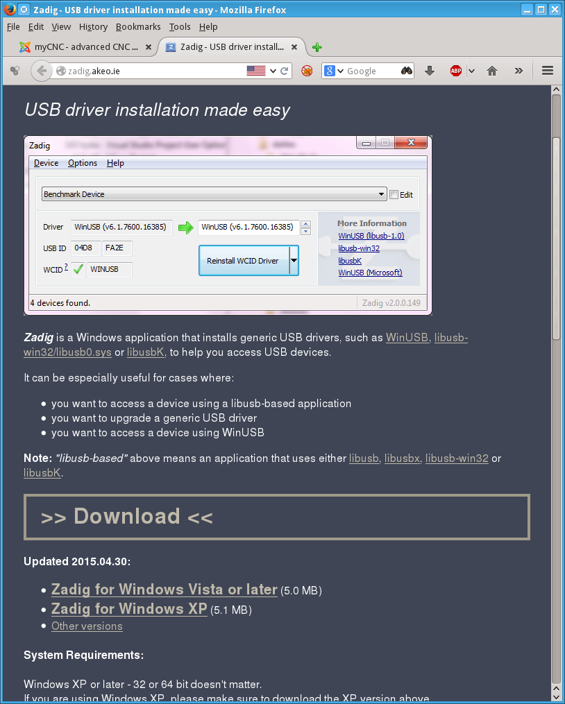
1. Download "Zadig" software from http://zadig.akeo.ie/
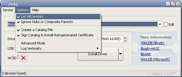
2. Run the utility, select "Options menu" and check menu "List All Devices"
3. Select "USB HID" device in the list (Check USB ID "10CE:EB70)
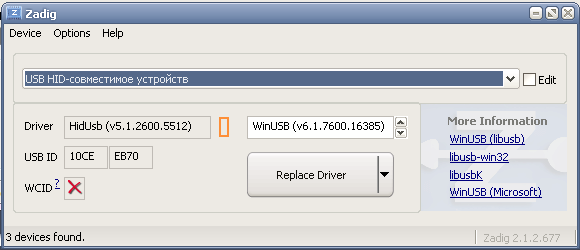
4. Select "WinUSB" driver and press "Replace Driver" button, confirm river changes.
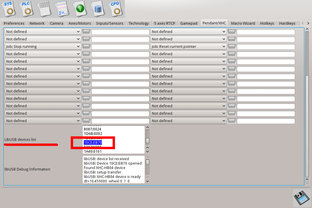
5. Restart myCNC software. Open settings dialog "Pendant/XHC", check if device "10CE:EB70" is
present in "LibUSB devices list" window. If device is present, myCNC software should get access to XHC Pendant control over "libusb" driver.
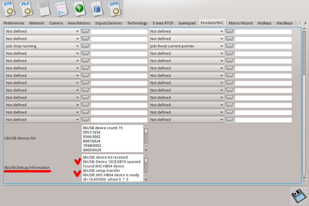
6. Check messages in "libUSB Debug Information". There are should be messages:
"libUSB: Device 10CE:EB70 opened"
"libUSB:XHC-HB04 device is ready"
7. Now myCNC software ready to receive button press events from XHC Pendant. Handlers for each button should be configured through this setup dialog. Let's setup a few XHC buttons as example.
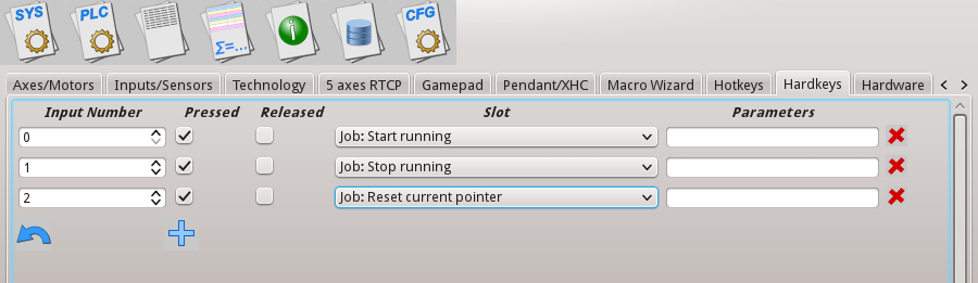
7.1 Press button "Reset" on WHB04-L Pendant panel. Find led highlighed on XHC setup dialog. Assign slot "Job: Reset current pointer" for this button.
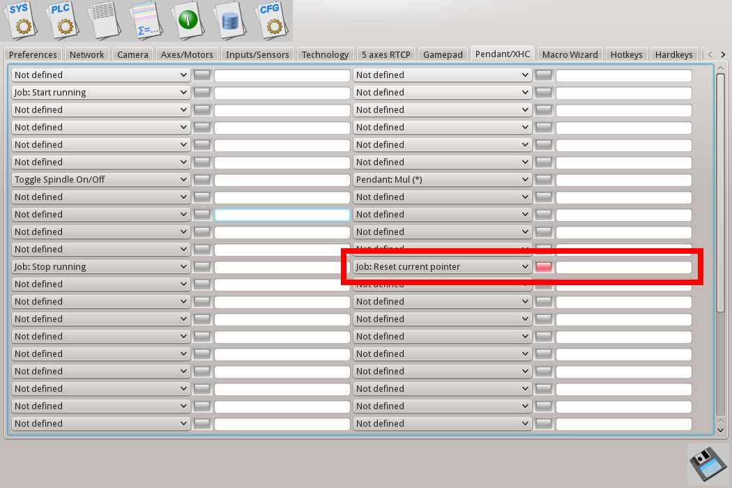
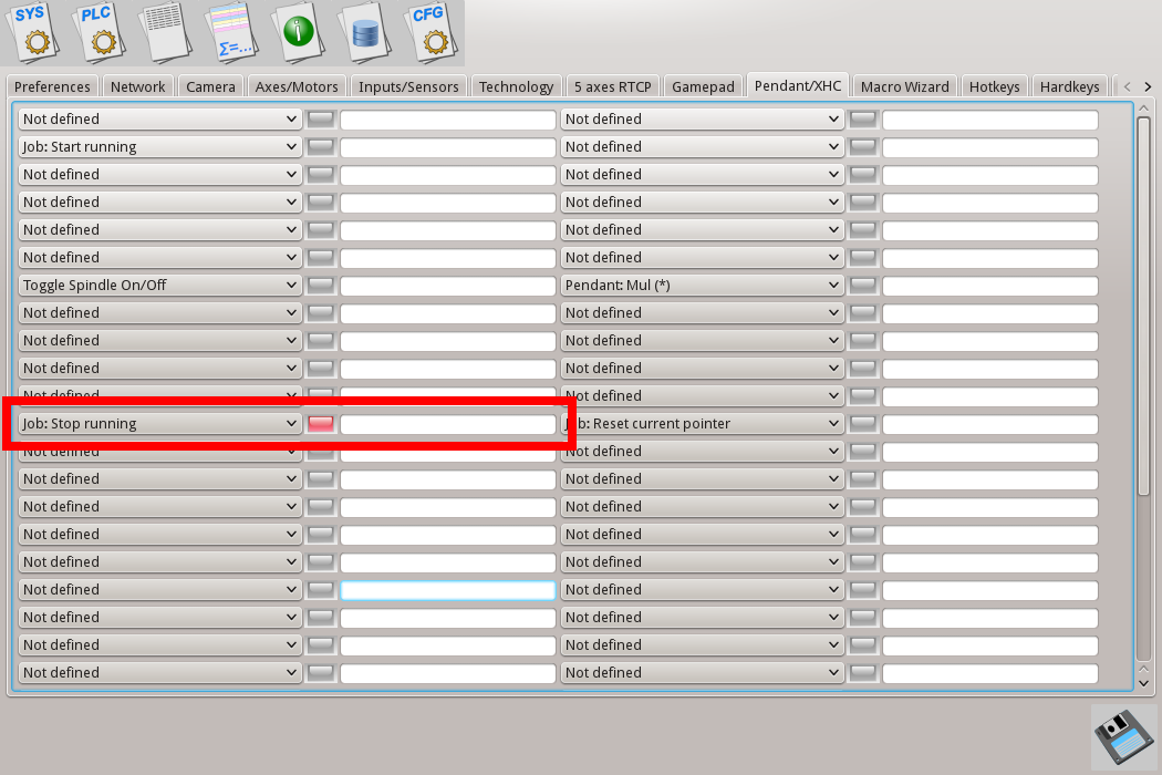
7.2 Press button "Stop" on WHB04-L Pendant panel. Find led highlighed on XHC setup dialog. Assign slot "Job: Stop running" for this button.
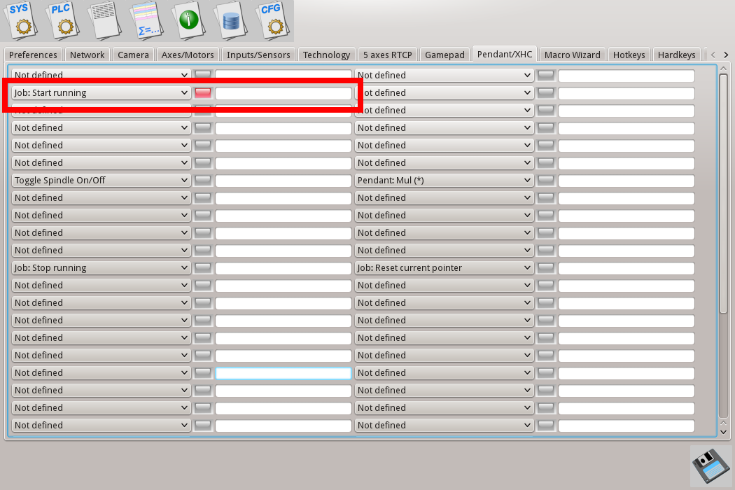
7.3 Press button "Start" on WHB04-L Pendant panel. Find led highlighed on XHC setup dialog. Assign slot "Job: Start running" for this button.
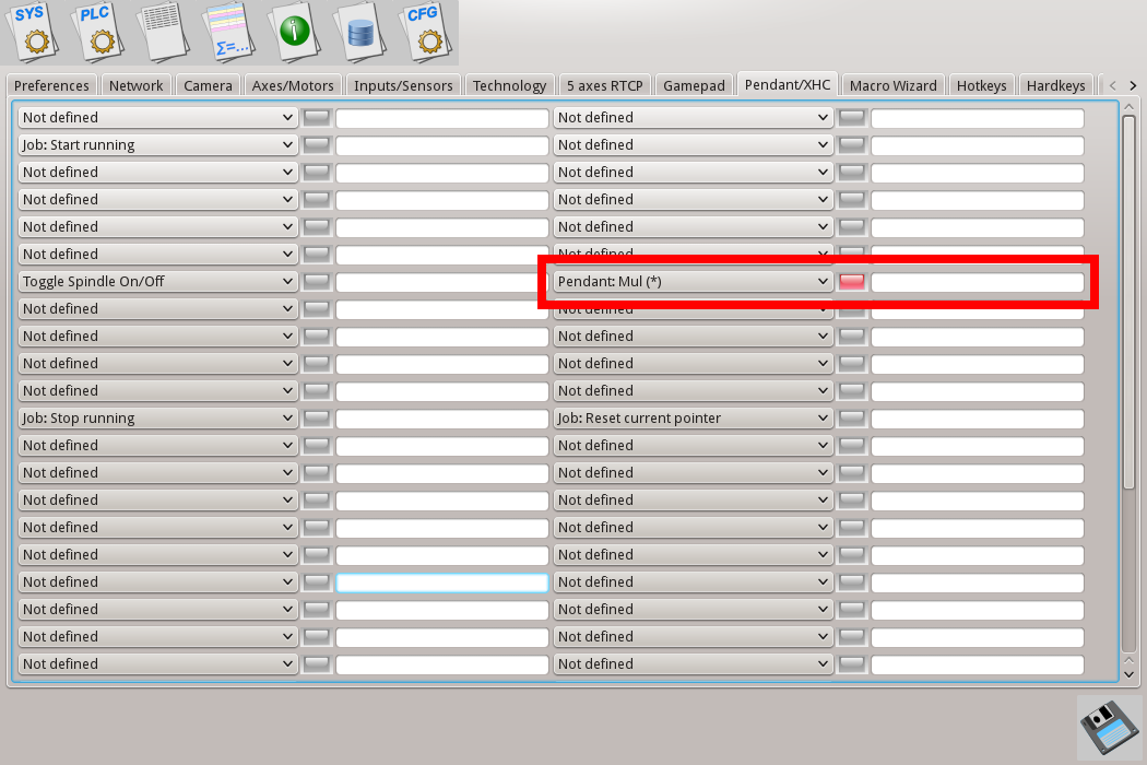
7.4 Press button "Step++" on WHB04-L Pendant panel. Find led highlighed on XHC setup dialog. Assign slot "Pendant Mul(*)" for this button. Pressing on this button will change Pendant wheel step.
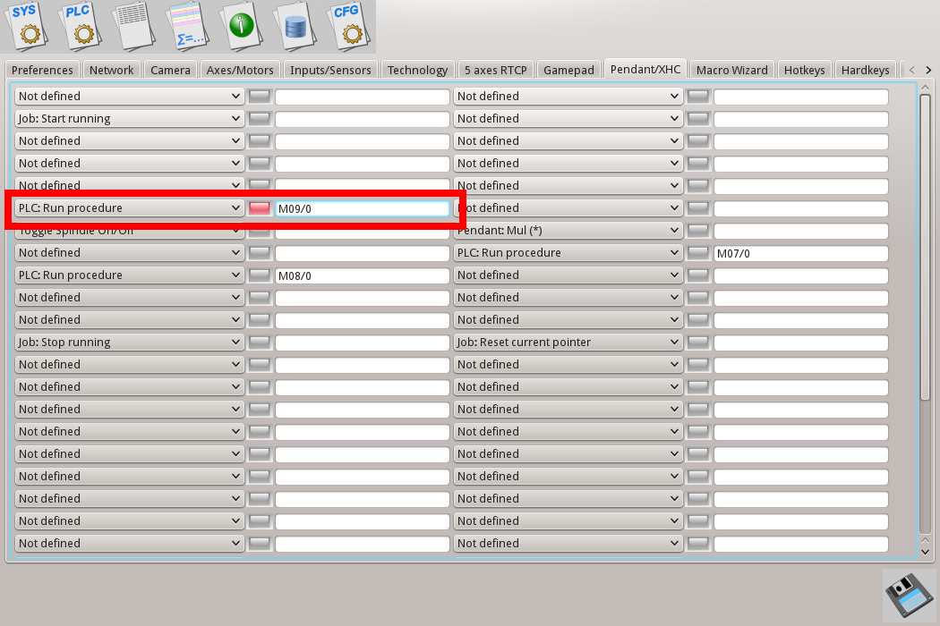
7.5 Assign M09 PLC procedure to button "Macro-1". Press button "Macro-1" on WHB04-L Pendant panel. Find led highlighed on XHC setup dialog. Assign slot "PLC: Run procedure" and fill parameter with "M09/0". It means load PLC procedure "M09" and initialize PLC parameter to "0". PLC procedure parameter value desn't matter for this example, however parameter is mandatory according command syntax and should be given in command line.
7.6 Press "Save" button to save chnages, resteart myCNC software.
Hardkeys definition.
Binary inputs can be used as Pendant control buttons. Number of functions can be assigned flexibly to any of binary input, "Button-Press" and/or "Button-Release" events.
Dialog for hardkey assignment helps to add assignments, chnage binary input number, "presse" or "release" event and select Slot Procedure to run.
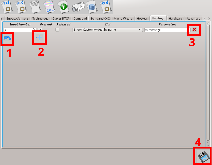
- "Undo" button. Till "Save" button wasn't pressed it's possible to roll-back to previous saved hardkeys settings by pressing this button.
- "Add" button. Press this button to add new hardjey configuration line. After new line added, it should be configured and saved. myCNC softwrae should be resterted to hardkey configuration takes effect.
- "Remove" button. Press this button to remove selected hardkey configuration from hardkeys list.
- "Save" button. Press this button to save hardkeys configuration to disk. Please notice that changes will take effect after myCNC software restart.
- Input Number - binary input number assigned as Hardkey
- "Pressed" - select this checkbox if "Key-Press" event should be handled
- "Released" - select this checkbox if "Key-Release" event should be handled
- "Slot" - handler procedure
- "Parameters" - if handle procedure requires parameters it can be set in this edit line
Slot List
| Slot name | Slot description |
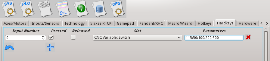
| CNC Variable: Switch | Switch CNC variable between several predefined values. Parameters divided by ";". The first parameter is CNC variable address (Index in global array). Rest parameters are values list. If slot activated (hardkey pressed/released) CNC variable value will be switched between given values |
|
By pressing key attached to binary input#0, CNC variable #115 will be changed between values "50", "100", "200", "500" |
|
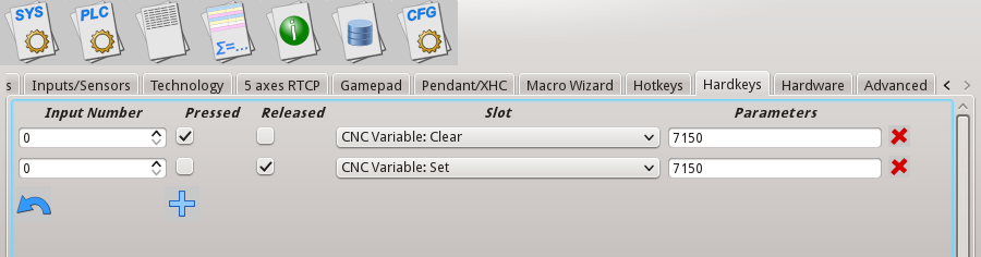
| CNC Variable: Clear | Clear (Rreset to "0") given CNC variable. Parameters contains address of CNC Variable in Global variables array. |
| CNC Variable: Set | Set (Write "1") given CNC variable. Parameters contains address of CNC Variable in Global variables array. |
|
If Key attached to binary input#0 is pressed, "0" value is written to CNC variable #7150, |
|
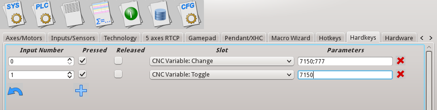
| CNC Variable: Toggle | Switch CNC variable between values "0", "1". Parameters contains address of CNC Variable in Global variables array. If slot activated (hardkey pressed/released) CNC variable value will be switched between given values |
| CNC Variable: Change | Write to CNC variable given value. Parameters contains address of CNC Variable in Global variables array and the value should written to. Parameters divided by ";" |
|
If Key #0 pressed, value "777" will be written to CNC Variable #7150 |
|
| File Open |
Open File Open dialog |
| File Open DXF/HPGL |
Open dialog for import DXF/HPGL files |
| Job: Play 1 line | Play (Run) 1 line from current NC line number. |
| Job: Play 1 line backward | Play (Run) 1 line from current NC line number in backward direction. |
| Job: Run G-code | Run G-code commands given in Parameters. Several G-code lines are divided by ";" |
|
|
|
| Job: Start running | Play (Run) NC (g-code) program from current NC line. |
| Job: Start running backward | Play (Run) NC (g-code) program from current NC line in backward direction. |
| Job: Stop running | Stop (Pause) running NC program. |
| Job: Reset current pointer | Reset Current NC line (NC pointer) to the first position. |
|
Pressing "Key #0" - start running G-code program from current NC line |
|
|
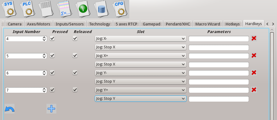
Jog: X- |
Start Jog in X- direction Start Jog in X+ direction Stop Jog in X direction Start Jog in Y- direction Start Jog in Y+ direction Stop Jog in Y direction Start Jog in Z- direction Start Jog in Z+ direction Stop Jog in Z direction Start Jog in A- direction Start Jog in A+ direction Stop Jog in A direction Start Jog in B- direction Start Jog in B+ direction Stop Jog in B direction Start Jog in C- direction Start Jog in C+ direction Stop Jog in C direction |
|
Keys attached to binary inputs #4, #5, #6, #7 are programmed as XY Joystick for Jog in XY direction. |
|
| Jog Speed Override: inc Jog Speed Override: dec |
Increase "Jog Override" variable Decrease "Jog Override" variable |
| Speed Override: inc Speed Override: dec |
|
| Spindle Speed: inc Spindle Speed: dec |
|
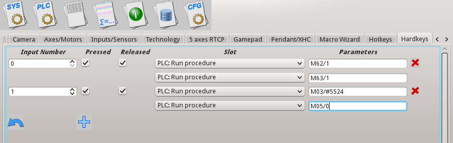
| PLC: Run procedure | Direct run PLC procedure. Parameters contain PLC name and Parameter value divided by "/" |
| PLC: Run external unit procedure | If using multi-device configuration, direct run PLC procedure from additional controller. Parameters contain device ID number, PLC name and Parameter value divided by "/" |
|
Press Key#0 to turn ON relay #1 (PLC procedure M62 turn ON binary output, Parameter=1 defines output number to turn ON) |
|
| Pendant: Axis (*) | Cycle switch "Pendant Control" Axis select between axes X, Y, Z, A, B, C. If "Max value reached (Axis C), next will me Min value (Axis X) |
| Pendant: Mul (*) | Cycle switch "Pendant Control" Step select between "0.001", "0.01", "0.1", "1". If Max value ("1") reached, next will be Min value ("0.001") |
| Pendant: Wheel CW | Emulate rotation Hand Wheel CW 1 step |
| Pendant: Wheel CCW | Emulate rotation Hand Wheel CCW 1 step |
| Pendant: Mul increment Pendant: Mul decrement |
Increase "Pendant Control" Step between "0.001", "0.01", "0.1", "1". Max value is ("1"), no changed if press more. Decrease "Pendant Control" Step between "1", "0.1", "0.01", "0.001". Min value is ("0.001"), no changed if press more. |
| Pendant: Axis change+ Pendant: Axis change- |
Change "Pendant Control" Axis between OFF, X, Y, Z, A, B, C. If "C" reached, no change if press more. Change "Pendant Control" Axis between C, B, A, Z, Y, X, OFF. If "OFF" reached, no change if press more. |
| Pendant0: x0.001 Pendant0: x0.01 Pendant0: x0.1 Pendant0: x1 |
Set "Pendant Control" Step value to "0.001". Set "Pendant Control" Step value to "0.01". Set "Pendant Control" Step value to "0.1". Set "Pendant Control" Step value to "1". |
| Pendant0: Axis Off Pendant0: Axis X Pendant0: Axis Y Pendant0: Axis Z Pendant0: Axis A Pendant0: Axis B Pendant0: Axis C |
Set "Pendant Control" Axis to "OFF". Set "Pendant Control" Axis to "X". Set "Pendant Control" Axis to "Y". Set "Pendant Control" Axis to "Z". Set "Pendant Control" Axis to "A". Set "Pendant Control" Axis to "B". Set "Pendant Control" Axis to "C". |
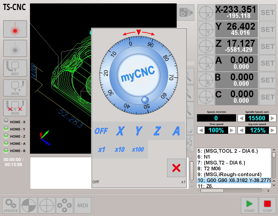
| Show: Pendant control widget Show: MDI widget Show: Config widget |
Show Pendant control emulation window Show MDI (Manual data input) window Show User configuration window |
|
Pendant window shown. MDI window shown
User settings window shown. |
|
| Show: Editor widget Show: Work widget |
Show Editor window Show Main Work window |
| Show: Library Shape widget Show: Diagnostic widget Show: User widget Show: Centring widget Show: Rotation widget Show: Saw Cutting widget |
Show Library Shapes window Show Custom-Defined Diagnostic window Show Custom-Defined User Window Show Centring (Center Probing) window Show Rotate NC program window Show Saw Cutting macro generator window |
| Show: Custom widget by name Toggle: Custom widget by name Hide: Custom widget by name |
Show custom wnidow defined in cnc-screen.xml by name ID Toggle (switch hide-show-hide-..) custom window defined in cnc-screen.xml by name ID Hide custom window defined in cnc-screen.xml by name ID |
Move to Toolpath Tie Toolpath position to current work position |
|
| Toggle Machine/Work DRO (if applicable) Toggle Jog enable/disable Toggle Jog mode unlimited/step Toggle Soft Limits enable/disable Toggle Flood On/Off Toggle Spindle On/Off Toggle Constant Velocity (CV) On/Off |
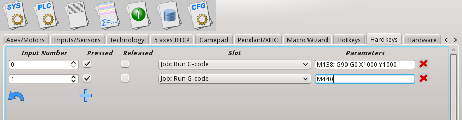 Pressing "Key #0" will run Homing Z, X, Y procedure (which is macro M138), then move to position (1000,1000)