ET5, using encoder inputs as General purpose inputs (ru)
- 9 years ago.
ET5, using encoder inputs as General purpose inputs
ET5 control board contains 12 encoder inputs. Each encoder inputs has input signals A, B, Z. All encoder input pins can be mapped into General Purpose inputs address space and used as binary input .
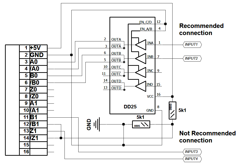
Encoder inputs are designed as RS422 Differential Line Driver inputs. That means each input is 2 pins and it accepts differential signal that meets ANSI Standard EIA/TIA-422-B. It's highly recommened to use "Differential Line Driver" chips to produce compatible signals. However a simple schematic with 2 resistors can be used as well. Possible connection to ET5 encoder inputs connector shown below.
Input1, Input2 - Recommended connection to ecnoder inputs.
Input2, Input3 - Possible, but not recommended connection.
Each encoder input pin (36 pins in total) is connected to 16-bits ET5-Enocder registers.
Encoder pins connection to ET5-Encoder registers is shown in a table below.
| Connector# | Pins# | Encoder# | Signal names | ET5-Encoder register address (Port.Bit) |
| X10 | 3, 4 | 0 | A, /A | 1.7 |
| X10 | 5, 6 | 0 | B, /B | 1.6 |
| X10 | 7, 8 | 0 | Z, /Z | 1.5 |
| X10 | 9, 10 | 6 | A, /A | 0.5 |
| X10 | 11, 12 | 6 | B, /B | 0.4 |
| X10 | 13, 14 | 6 | Z, /Z | 0.3 |
| X11 | 3, 4 | 1 | A, /A | 1.4 |
| X11 | 5, 6 | 1 | B, /B | 1.3 |
| X11 | 7, 8 | 1 | Z, /Z | 1.2 |
| X11 | 9, 10 | 7 | A, /A | 0.2 |
| X11 | 11, 12 | 7 | B, /B | 0.1 |
| X11 | 13, 14 | 7 | Z, /Z | 0.0 |
| X12 | 3, 4 | 2 | A, /A | 1.1 |
| X12 | 5, 6 | 2 | B, /B | 1.0 |
| X12 | 7, 8 | 2 | Z, /Z | 0.15 |
| X12 | 9, 10 | 8 | A, /A | 2.11 |
| X12 | 11, 12 | 8 | B, /B | 2.10 |
| X12 | 13, 14 | 8 | Z, /Z | 2.9 |
| X13 | 3, 4 | 3 | A, /A | 0.14 |
| X13 | 5, 6 | 3 | B, /B | 0.13 |
| X13 | 7, 8 | 3 | Z, /Z | 0.12 |
| X13 | 9, 10 | 9 | A, /A | 2.8 |
| X13 | 11, 12 | 9 | B, /B | 2.7 |
| X13 | 13, 14 | 9 | Z, /Z | 2.6 |
| X14 | 3, 4 | 4 | A, /A | 0.11 |
| X14 | 5, 6 | 4 | B, /B | 0.10 |
| X14 | 7, 8 | 4 | Z, /Z | 0.9 |
| X14 | 9, 10 | 10 | A, /A | 2.5 |
| X14 | 11, 12 | 10 | B, /B | 2.4 |
| X14 | 13, 14 | 10 | Z, /Z | 2.3 |
| X15 | 3, 4 | 5 | A, /A | 0.8 |
| X15 | 5, 6 | 5 | B, /B | 0.7 |
| X15 | 7, 8 | 5 | Z, /Z | 0.6 |
| X15 | 9, 10 | 11 | A, /A | 2.2 |
| X15 | 11, 12 | 11 | B, /B | 2.1 |
| X15 | 13, 14 | 11 | Z, /Z | 2.0 |
All myCNC controllers contain address space for 10x 16-bits general purpose input registers (address space for 160 input pins). Each ET5-Encoder register can be mapped to any of general purpose Input register.
IO Mapping Setuip dialog is shown below.
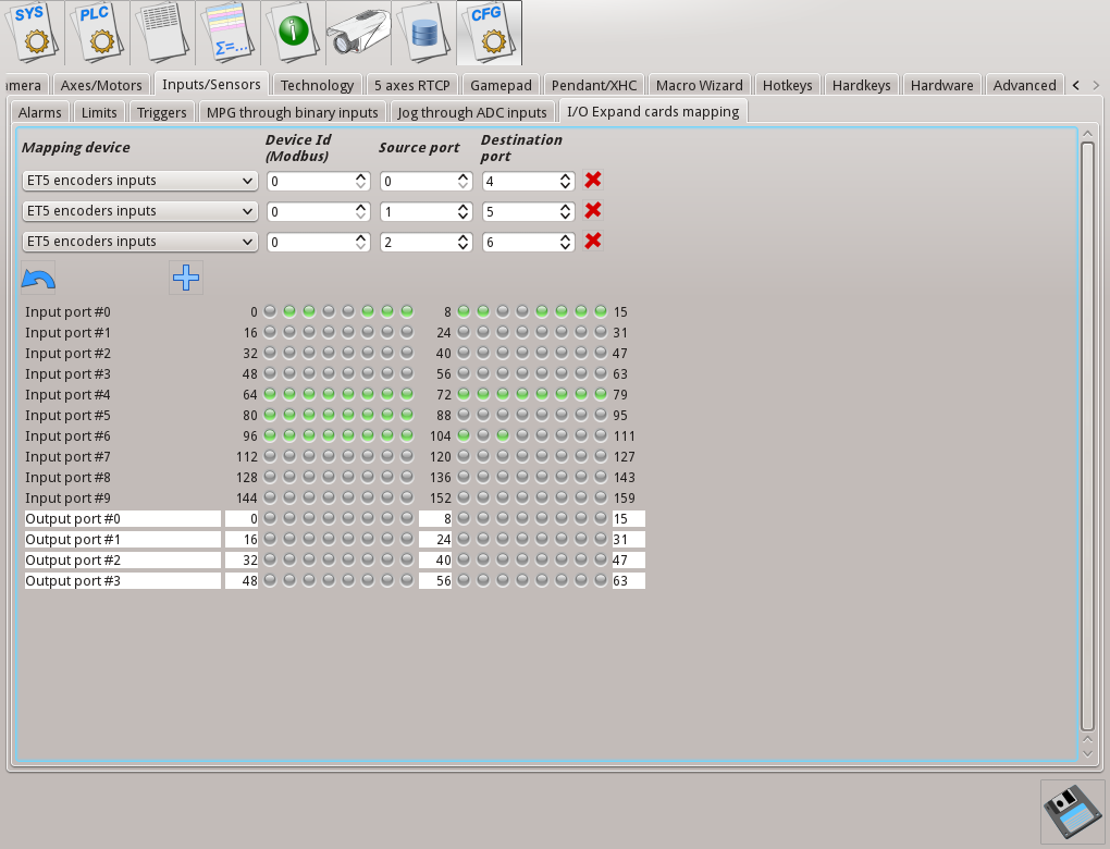
On a picture -
- ET5-Encoder port#0 is mapped to Input port #4 (port bits (0...16) are available on addresses (64...79)
- ET5-Encoder port#1 is mapped to Input port #5 (port bits (0...16) are available on addresses(80...95)
- ET5-Encoder port#2 is mapped to Input port #6 (port bits (0...16) are available on addresses(96...111)
Example:
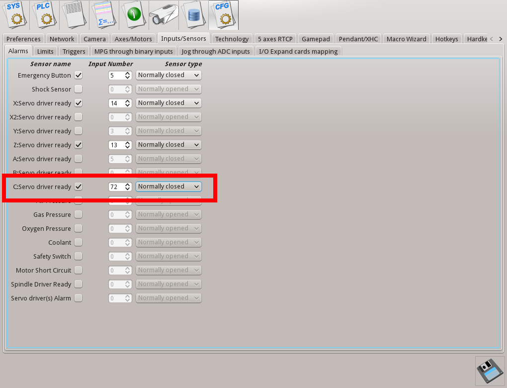
We need to use X15 pins 3,4 (signal A, /A of Encoder#5) as "Servo Driver C Ready" signal.
To get this:
- Encoder#5, A(/A) signal is attached to ET5-Encoder Register#0, bit 8
- Map ET5-Encoder Register#0 to Input Register #4.
- Bit#8 ET5-Encoder Register#0 now is available by address #(64+8)=#72
- Setup Input #72 as "Servo driver C Ready
- Restart myCNC software to apply the changes
{avsplayer videoid=7}