WARNING: Unlike updating the myCNC software, the firmware CANNOT be downgraded after a reflash. The myCNC team recommends reflashing the control board firmware as a last resort only, and recommends seeking an explicit confirmation from the support team that the firmware reflash is warranted in order to avoid issues.
NOTE: Make sure to select the firmware for the correct version/revision of your board! Firmware for ET7 boards (R1-R3) and ET7 boards (R4-R6, also known as the ET9) are DIFFERENT. Flashing incorrect version of the firmware will result in a non-functional board. If you're unsure of your board version, please contact myCNC Technical Support prior to the reflash:

myCNC-ET7 reflashing procedure may take up to 3 minutes.
To reflash the board:
1. Plug in the 24V DC power supply
2. Plug in the micro-USB cable into the ET7 controller & a Host Computer with myCNC installed. NOTE: The micro-USB cable must be capable of data transfer (not a simple micro-USB charging cable)
3. Close jumpers J5(reset) & J6(programming) on the controller board
4. Open (remove) the J5 jumper.

5. Open myCNC software on Host computer (Settings > Support Tab)
6. “Select board” set to “myCNC-ET7”
7. Select “Firmware version” from “Release”, “Night build” or “Testing” (“Release” is recommended)
8. “UART port” select port with FT232 attached
9. Baud Rate set to “115200” for ET7; other baudrate can be selected in case of problems on 115200 speed
10. Press “Update Firmware” button, Firmware download and reflashing process will be started
11. If “Sector 0; +” message is shown in the debug window, the reflashing process has finished successfully.
12. Remove all jumpers (J5, J6) and restart the board.


If the reflashing process failed, please check your internet connection and the micro-USB connection, and then repeat the reflashing procedure from Step 3.
myCNC-ET7 controller board
myCNC-ET7 controller specification
| Number of motor outputs |
6 |
| Motor driver outputs |
pulse-dir, |
| Maximum pulse frequency |
3 MHz |
| Binary inputs |
16x galvanic isolation, |
| Encoder inputs |
3x incremental encoder inputs, |
| Binary outputs |
5x - pluggable relays 10A, NO/NC contacts |
| PWM outputs |
3x - open collector, 24V, 0.25A, |
| ADC inputs |
2x - 0...10V range, differential inputs, fully galvanic isolated |
| DAC output |
1x - 0...10V (for spindle speed control and relative applications) |
| RS485/RS422 |
1x RS422 full duplex serial communication |
| External operator panel connector |
Up to 25 external keys Custom panels (available on bulk orders of 10+ panels) can be customized to include up to 2 rotary encoders, up to 2 double-axes joysticks OR |
| Power supply outputs for control computer |
2x DC-DC converters 5V 1.5A |
Please find the full ET7 control board connectors descriptions on our online documentation website
ET7 top view

Power supply connection
myCNC-ET7 control board uses 24VDC . The board contains 4 pins for connection +24V (joined internally) and a number of GND pins for convenient connection of external devices. Power Supply 24V DC and +24V and GND pins are shown on a picture below:

Pulse-Dir outputs
ET7 has 6 channel pulse/dir outputs, 3MHz max pulses frequency.
ET7 pulse dir outputs conform to the RS422 standard and are compatible with most of servo and stepper drivers (line driver with paraphase signals of positive and negative polarity). Internal schematic for pulse-dir is shown on a picture below.
The pulse/dir schematic is shown below: 

ET7 Output pins
ET7 board contains 19 output pins-
-
5 relay outputs (OUT#11 … OUT#15)
-
11 open collector outputs (OUT#0 … OUT#10)
-
3 PWM outputs (PWM#1, PWM#2, PWM#3)
WARNING: ET7 board rev.1,2 has Output pin names printed on Bottom side of the board.
These names are NOT correct and differ from actual output addresses.
Please check the table below to find out the actual output address
| SILK print | Actual Output Pin Address |
|---|---|
| OUT0 | OUT0 |
| OUT1 | OUT1 |
| OUT2 | OUT2 |
| OUT3 | OUT3 |
| OUT4 | OUT4 |
| OUT5 | OUT5 |
| OUT6 | OUT6 |
| OUT7 | OUT7 |
| OUT8 | OUT8 |
| OUT9 | OUT9 |
| OUT10 | OUT10 |
| OUT11 | PWM1 |
| OUT12 | PWM2 |
| OUT13 | PWM3 |
| P0A | OUT11 (A) |
| P0B | OUT11 (B) |
| P0C | OUT11 (C) |
| P1A | OUT12 (A) |
| P1B | OUT12 (B) |
| P1C | OUT12 (C) |
| P2A | OUT13 (A) |
| P2B | OUT13 (B) |
| P2C | OUT13 (C) |
| P3A | OUT14 (A) |
| P3B | OUT14 (B) |
| P31 | OUT14 (C) |
| P4A | OUT15 (A) |
| P4B | OUT15 (B) |
| P41 | OUT15(C) |
Schematic for ET7 inputs & outputs is shown below


Galvanic isolated inputs
ET7 control board has 16 galvanic isolated binary inputs, 4 groups of 4 inputs each. Each group has separate power supply pins so inputs can be powered from different power sources. Using PNP and NPN sensors simultaneously is possible too.
Galvanic isolated inputs schematic is shown below

Connectors pinout for binary inputs is shown on a picture

Encoder Inputs
ET7 control board has 3 AB incremental encoder inputs with hardware implemented decoding. Max pulse frequency of encoder pulses is 3MHz. 6 encoder input signals are mapped to General purpose binary input addresses 20…25 and can be used as normal binary inputs. Encoder inputs are line driver differential signal compatible.
Encoder inputs schematic is shown below

Encoder inputs connector pinout is shown on a picture

ADC Inputs
myCNC-ET7 controller has 8 ADC inputs.
-
6 ADC inputs 0-5V range
-
2 ADC inputs with galvanic isolation for save and convenient connection of Arc Voltage signal from Power station. Galvanic isolated ADC inputs are 0..10V, so High Voltage Arc signal CANNOT be connected directly to ADC inputs, voltage divider is NEEDED.
The 0-5 V ADC inputs schematic is shown below: 
Isolated ADC inputs schematic is shown below:

Connectors pinout for ADC inputs is shown below

Non-isolated ADC inputs have a 0…5V Range. Connector with non-isolated ADC inputs also has the GND and +5V DC output pins for convenient potentiometer connection. Picture below shows an example for potentiometer connected to ADC2 input.

WARNING: The names for the ADC inputs printed at the bottom of the board are NOT correct.
Please consult the above schematics for the ADC0/ADC1 input locations.
Jumpers J1, J2, J3 and J4
In order for the board connections to function without an external power supply, the connections can be wired as to draw power from the +24V power supply of the board itself. In order to simplify the setup required for this procedure, jumpers 1 through 4 are put in place, as shown in the diagram below: 
Each jumper corresponds to its respective IN group number (for example, J4 for Group 4). In this way, in a configuration without an external power supply, the correct jumper for the group can be closed to supply power from the internal +24V. The switch should also short the wire to GNC (0V) in order for the circuit to be closed.
WARNING: If an external power supply is used, respective jumpers for the group should be OPEN
RS422/RS485 Bus
The myCNC-ET7 control board has a RS422/RS485 bus connector. Modbus ASCII/RTU and Hypertherm Serial communication interfaces are implemented in the myCNC-ET7 control board.
RS485 bus is enabled by default.
To enable RS422 interface you need to
-
close jumper J(#)
-
setup RS422 interface in the control software.
Please contact our support team if you need to use a RS422 bus.
A RS422/RS485 schematic is shown below 
RS422 connector pinout shown below. NOTE: While all of the RX/TX ports (RX A, RX B, TX A, TX B) are used for the RS422 connection (such as a Hypertherm machine), only RX A and RX B are utilized in an RS485 configuration.

DAC output
The myCNC-ET7 control board has a DAC output for spindle speed control. DAC output range is 1..12V Actual Max DAC voltage (ie 10V, 5V, 6V) can be set up in the myCNC control software.

Connection Examples
Stepper driver connection (4 axes)

3-wire NPN sensor connection example (external power supply)
Jumpers J1,J2,J3,J4 are all open.

3-wire PNP sensor connection example (external power supply)
Jumpers J1,J2,J3,J4 are all open.


3-wire NPN sensor connection example (internal power supply)
Internal power supply.
One of jumpers J1,J2,J3,J4 (J4 in case of this example) is closed.

3-wire PNP sensor connection example (internal power supply)
Internal power supply.
All of jumpers J1,J2,J3,J4 are open.

As the sensor requires a 24V power supply, it is necessary to connect it to the 24V port, not the 5V.
Switch connection example (internal power supply)
Jumper for selected group (one of J1,J2,J3,J4) is closed.
Common wire for 4 optocouple units is connected to internal +24V if Jumper is closed. Switch should short another optocouple input to GND (0V) to activate input pin.
J(#) - in this case, J4 - should be closed to connect optocouple pin to +24V. Switch should also short the wire to GNC(0V).

Switch connection example (external power supply)


Jumpers J1, J2, J3, J4 are all open
Spindle Speed control over DAC (0-10V) output

Board dimension

ET7 keypad board
We have a simple keypad board that can be used with the ET7 controller. Keypad board is connected to an ET7 controller through a `20 wires flat cable. Keypad contains 23 keys, 2x rotary encoders and double-axes simple resistive joystick.
ET7 control board interface to connect external keyboard is shown below

ET7 connector pinout

ET7 connector X4 pinout table
| X4 connector to External 25-keys keyboard | ||
|---|---|---|
| Pin# | Name | Comments |
| 1 | OUT A | Keyboard matrix output pins |
| 2 | OUT B | Keyboard matrix output pins |
| 3 | OUT C | Keyboard matrix output pins |
| 4 | OUT D | Keyboard matrix output pins |
| 5 | OUT E | Keyboard matrix output pins |
| 6 | IN #1 | Keyboard matrix input pins |
| 7 | IN #2 | Keyboard matrix input pins |
| 8 | IN #3 | Keyboard matrix input pins |
| 9 | IN #4 | Keyboard matrix input pins |
| 10 | IN #5 | Keyboard matrix input pins |
| 11 | E#0 | Encoder input (General purpose input) |
| 12 | E#1 | Encoder input (General purpose input) |
| 13 | E#2 | Encoder input (General purpose input) |
| 14 | E#3 | Encoder input (General purpose input) |
| 15 | ADC _ | |
| 16 | ADC _ | |
| 17 | ADC _ | |
| 18 | ADC _ | |
| 19 | GND | |
| 20 | 5V |
PDF: http://cnc42.com/downloads/et7-keypad-dimensions.pdf
DXF: http://cnc42.com/downloads/et7-keypad-dimensions.dxf

Each key, rotary encoder and the joystick functions can be programmed in configuration dialogs.
Schematics of the external ET7-KEY board is shown below

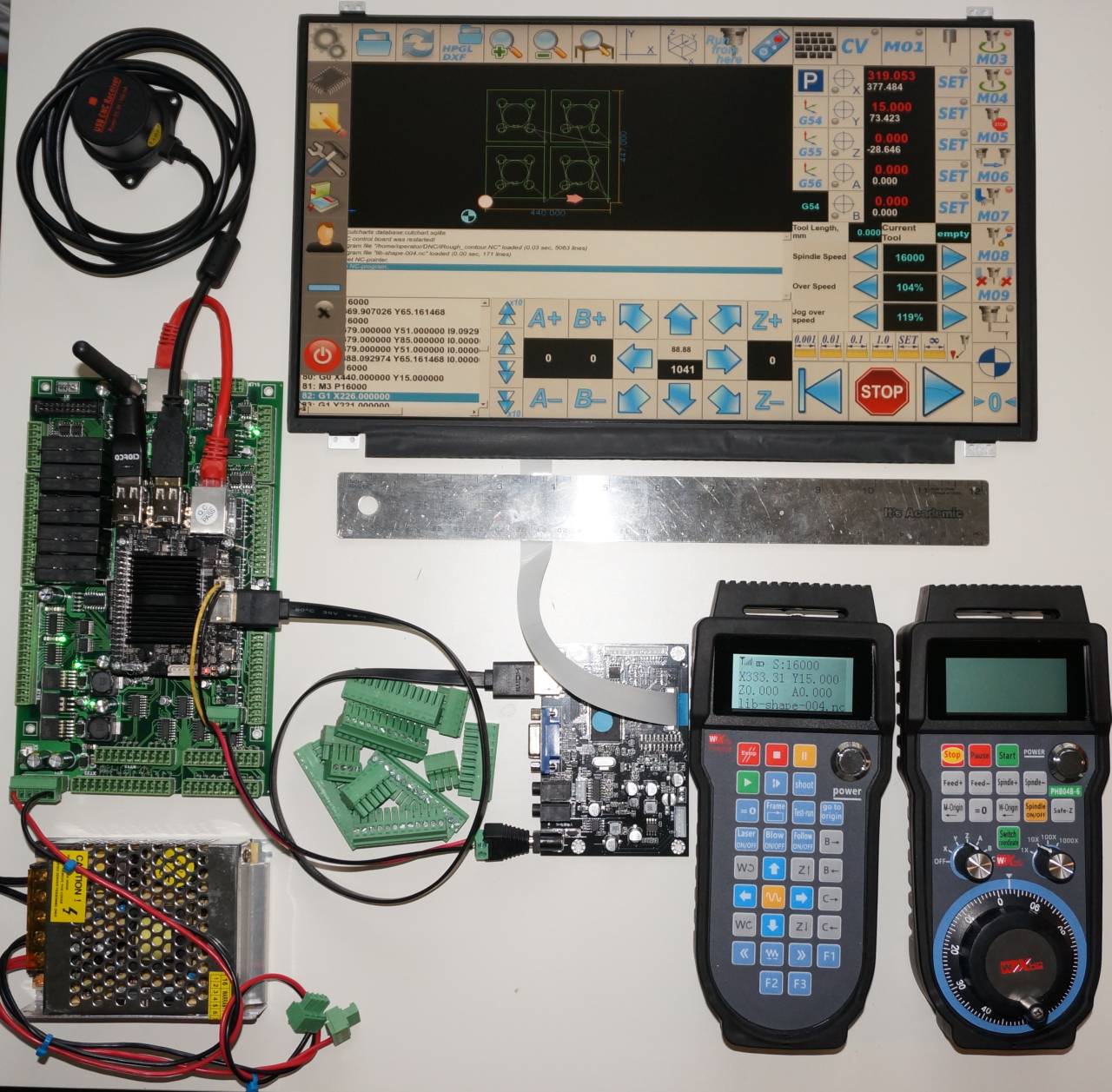
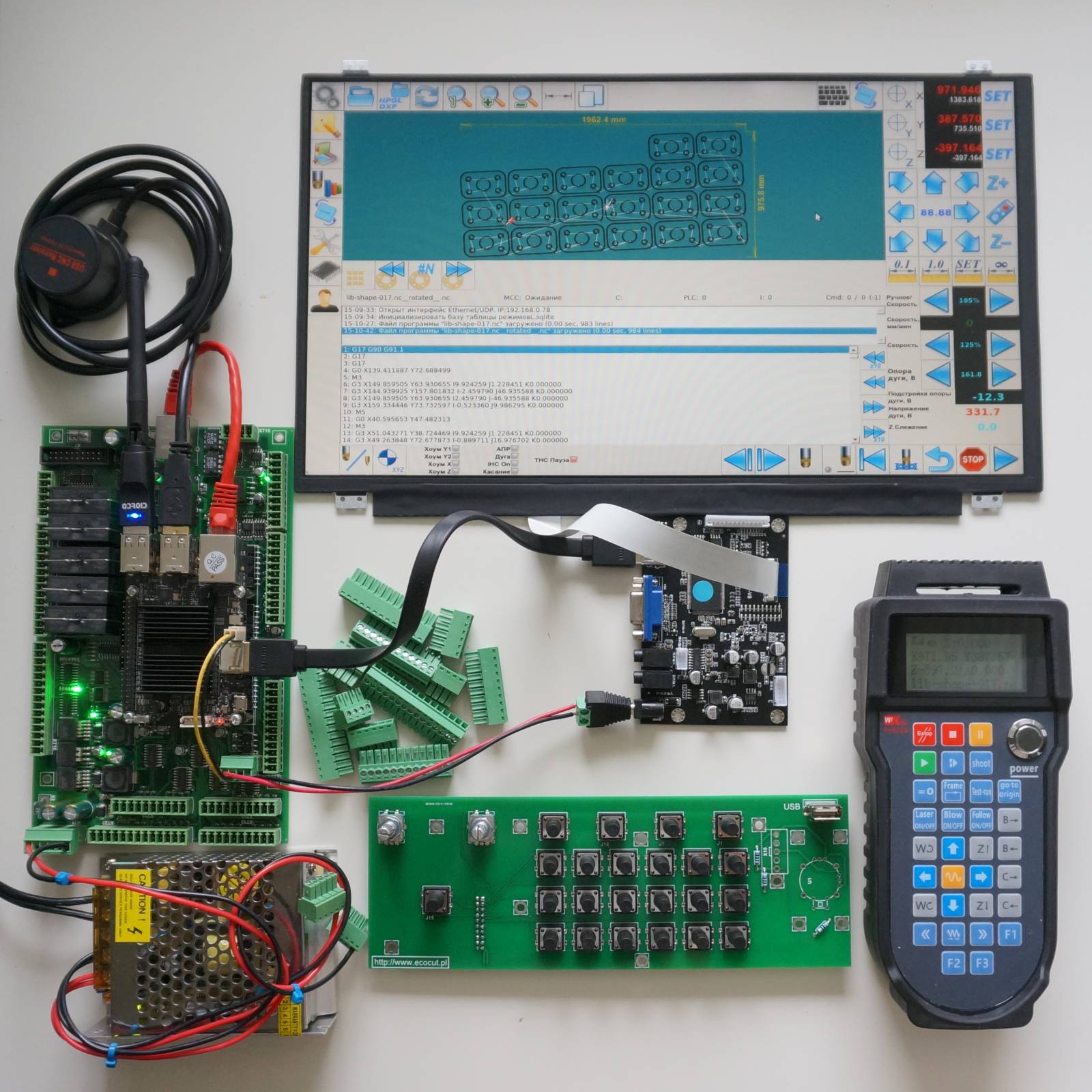
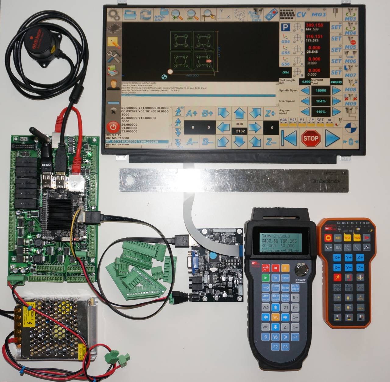
Control computer for myCNC-ET7
myCNC-ET7 board works under control of myCNC software. Control computer needs to build a complete CNC control system based on myCNC. It can either be a standard desktop/industrial computer with Linux or MS Windows OS installed
OR
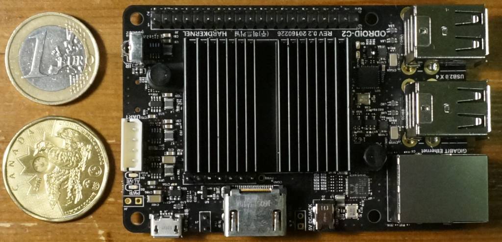
a small single board computer like the Odroid-C2, Odroid-XU4, or a Raspberry-Pi3/Pi2
myCNC-ET7 board contains a built-in DC-DC converter and mounting holes to install and power-up the Odroid/Raspberry computer board.

A standard monitor with an HDMI port can be connected to the Odroid-C2 computer board. Screen resolution up to 1920x1080 (Full HD) is supported. Fully functional Ubuntu 16.04 Linux and myCNC control software can be installed on the computer. NC code files can be uploaded to the computer through Wifi (Samba Server, FTP Server installed on the computer) or USB disks.
We can offer affordable 10"/15.6" screens with resistive touch to build a complete stand-alone CNC control kit.