Ethernet CNC controller myCNC-ET10
ET10BB Breakout board is designed specially for ET10 controller.
Pluggable terminal blocks are included in ET10 board package by default
MyCNC-ET10 Ethernet CNC Control board with integrated motion controller and PLC controller and rich peripherals.
myCNC-ET10 Controller board based on 204MHz 32bit ARM Cortex-M4 Processor and Altera FPGA logic.
Controller contains:
- Motion controller with true multi-axes line, arc, spiral, spline interpolators;
- Programmable Logic Controller;
- 6 channels pulse/dir outputs;
- 6 channels +/-10V DAC outputs for analogue servo-driver control;
- 6 channels incremental encoders inpiuts, 4 full ABC encoder inputs, 2 reduced AB encoder inputs;
- 48 binary inputs (if use with ET10BB breakout - all inputs have galvanic isolation, 12 groups of 4 binary inputs, compatible with NPN & PNP sensors);
- 24 binary outputs (if use with ET10BB breakout - all outputs are open collector, 24V 0.25A);
- 4 PWM outputs (if use with ET10BB breakout - all PWM outputs are open collector, 24V 0.25A);
- 8 ADC inputs (if use with ET10BB breakout - 7 ADC inputs are 0...5V range, 1 ADC is differential inpit, 0...30V range);
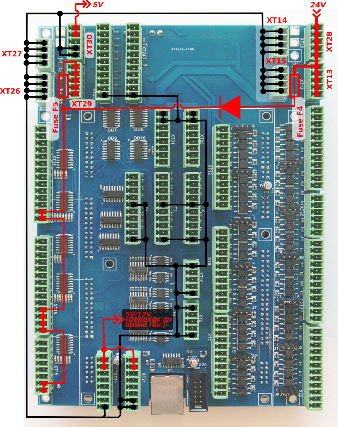
Power supply connection
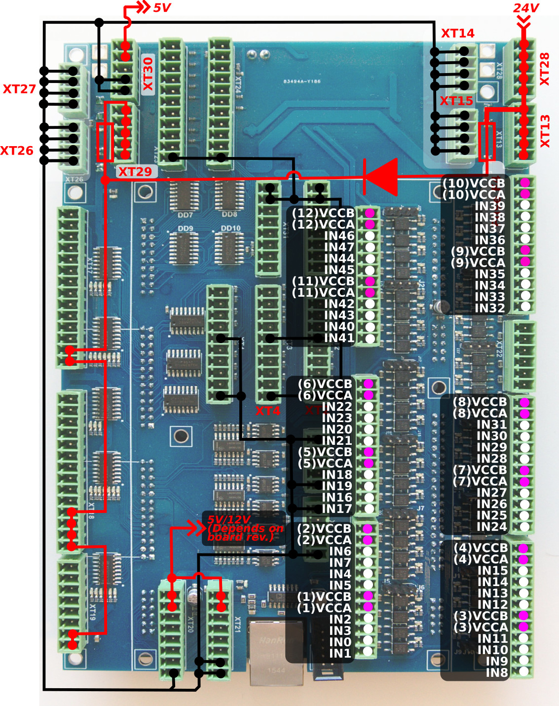
24VDC is used to supply myCNC-ET10 control board. The board contains 4 pins for connection +24V (joined internally) and a number of GND pins for convenient connection of external devices. The 24V DC Power Supply and +24V and GND pins are shown in the picture below.
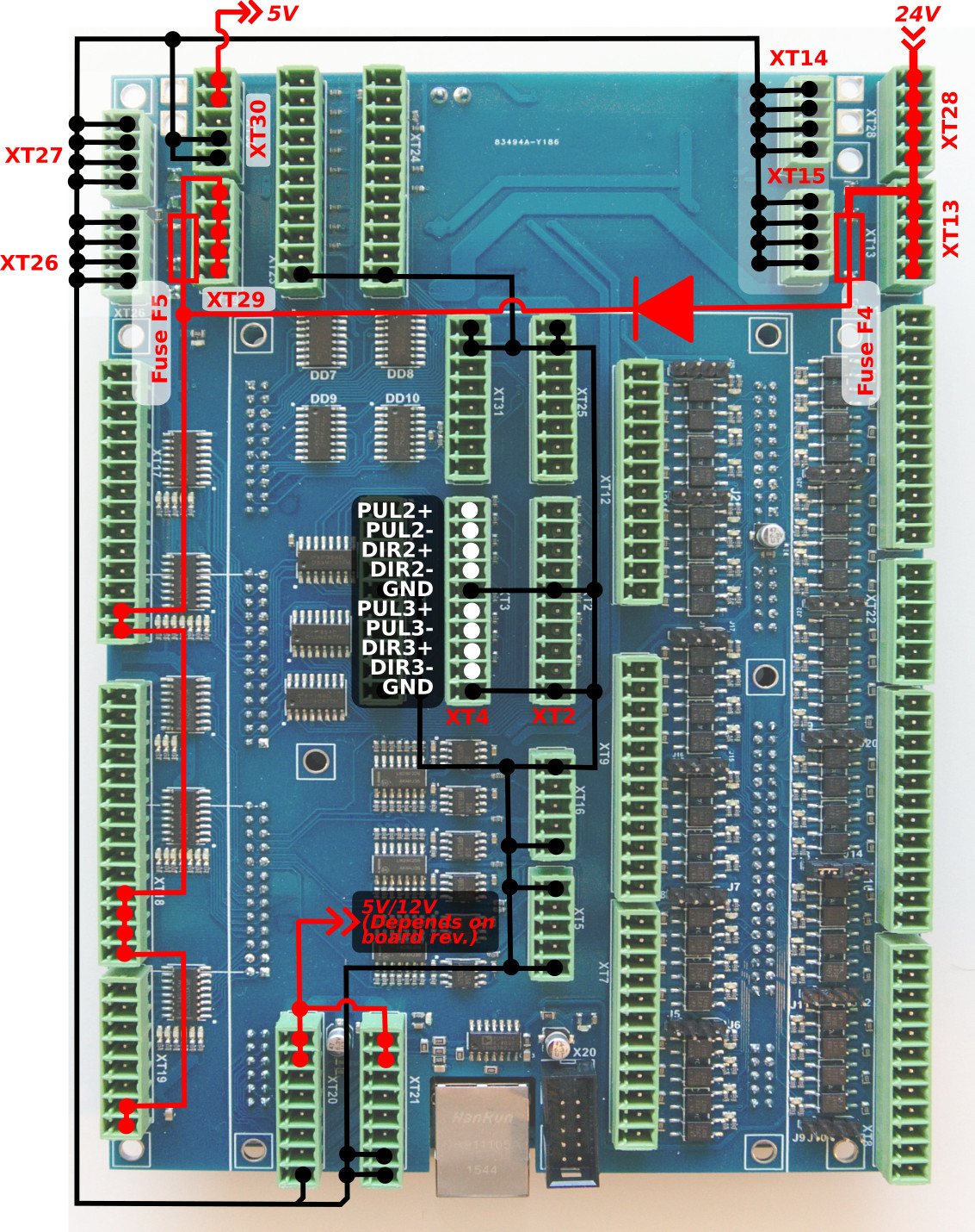
Pulse-Dir outputs
ET10 has 6 channel pulse/dir outputs, with the maximum pulse frequency of 3MHz.
ET10 pulse/dir outputs conform to the RS422 standard and are compatible with most of servo and stepper drivers (line driver with paraphase signals positive and negative polarity). Internal schematic for pulse-dir is shown in the picture below:

PULSE-DIR channels 0,1,4,5 pinout
PULSE-DIR channels 2,3 pinout
ET10 Output pins
ET15 board contains … output pins-
-
24 open collector outputs (OUT#0 … OUT#23)
-
4 PWM outputs (PWM#1, PWM#2, PWM#3, PWM#4)
An internal schematic is shown in the picture below. Darlington transistor array chips ULN2003 are used to buffer binary outputs in ET10. Each chip contains 7 transistors and handles up to 7 binary outputs. We recommend not to exceed 0.25A output current for each output pin (however ULN2003 maximum current is 0.5A according to the datasheet).

ET10 pinout for the outputs is shown below:
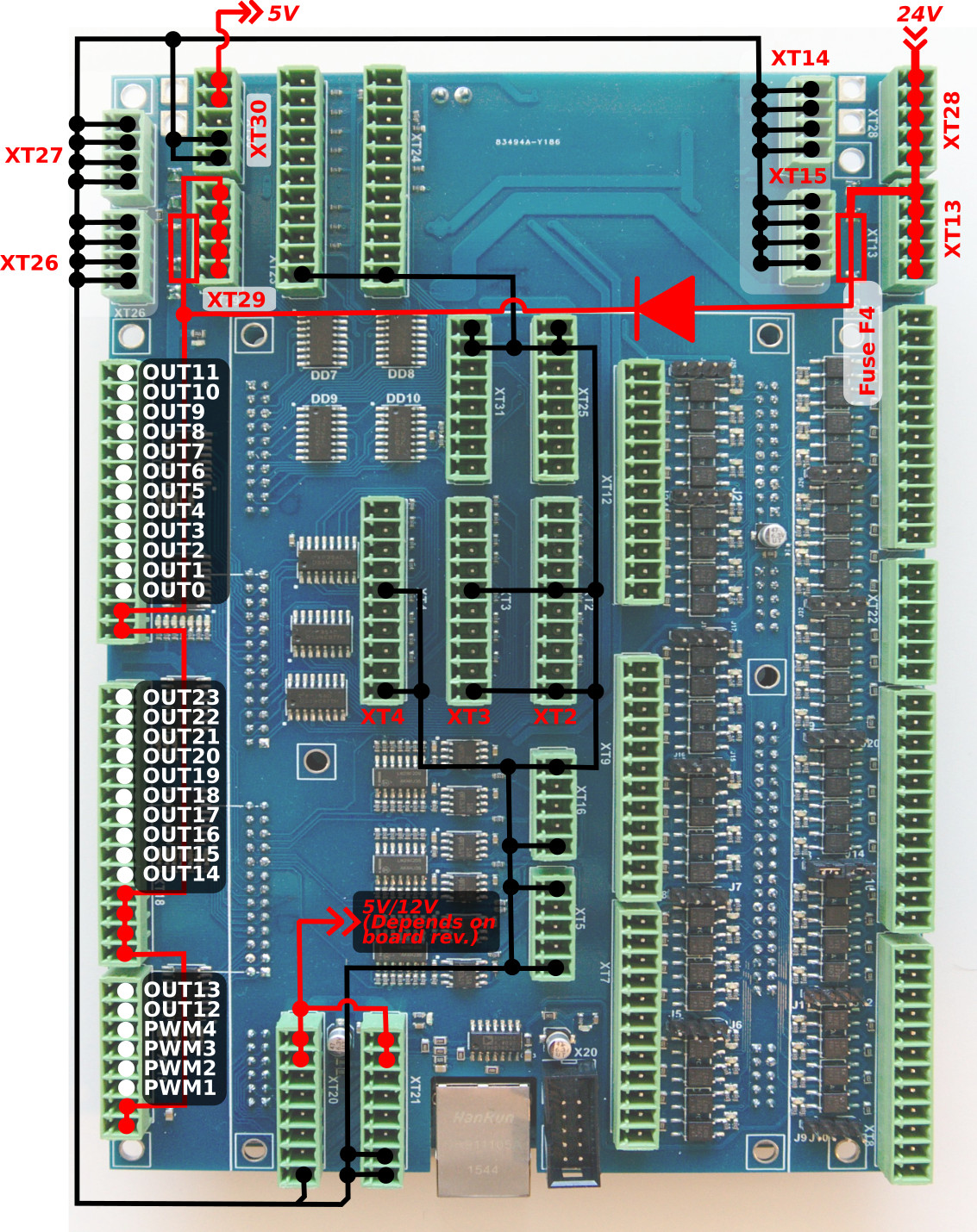
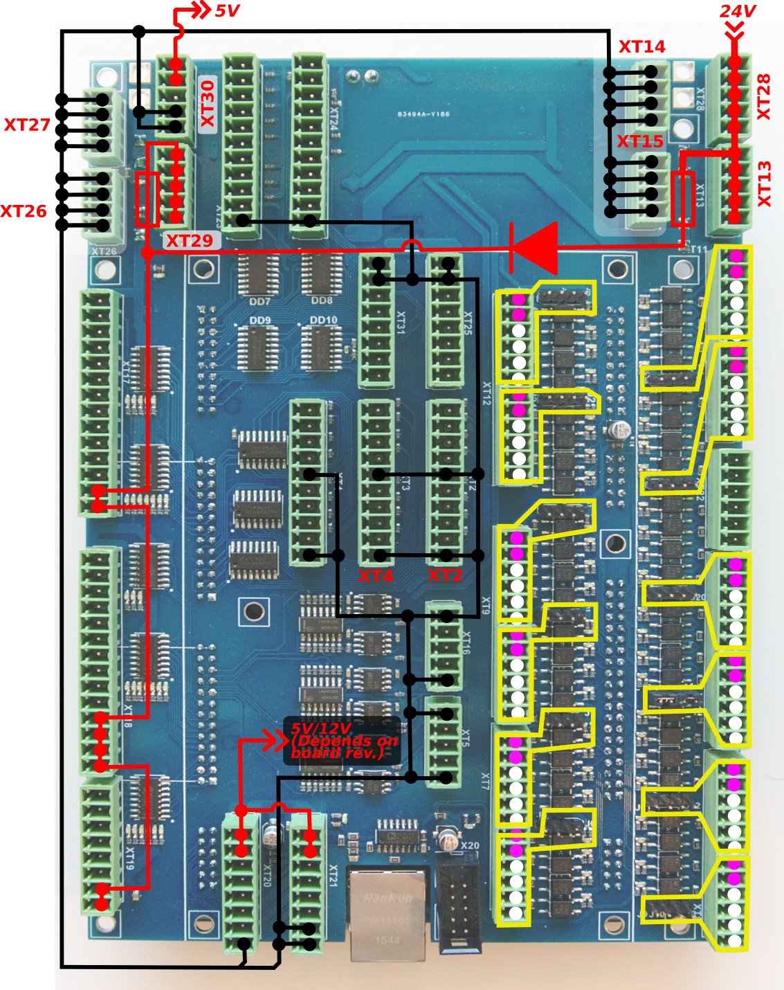
There are LED indicators for each Output and PWM pin on the ET10 board to control actual Output/PWM state. LEDs are highlighted in the picture below.

Galvanic isolated inputs
The ET10 control board has 48 galvanic isolated binary inputs, 12 groups of 4 inputs each. Each group has a common LED wire and separate power supply pins so inputs can be powered from different power sources. Using PNP and NPN sensors simultaneously is possible too. Schematic of the 4 inputs group is shown in the picture below.

Wires VCCB (common wire) and VCCA are used for external power supply connection. Beside external power supply, internal +24V DC can be used to supply input LEDs, if the correspondent jumpers are closed.
WARNING: If an external Power supply is used, corresponding jumpers for the group should be OPEN
Jumpers to use the internal power supply for each 4-inputs group are shown in the picture below
Connection Examples
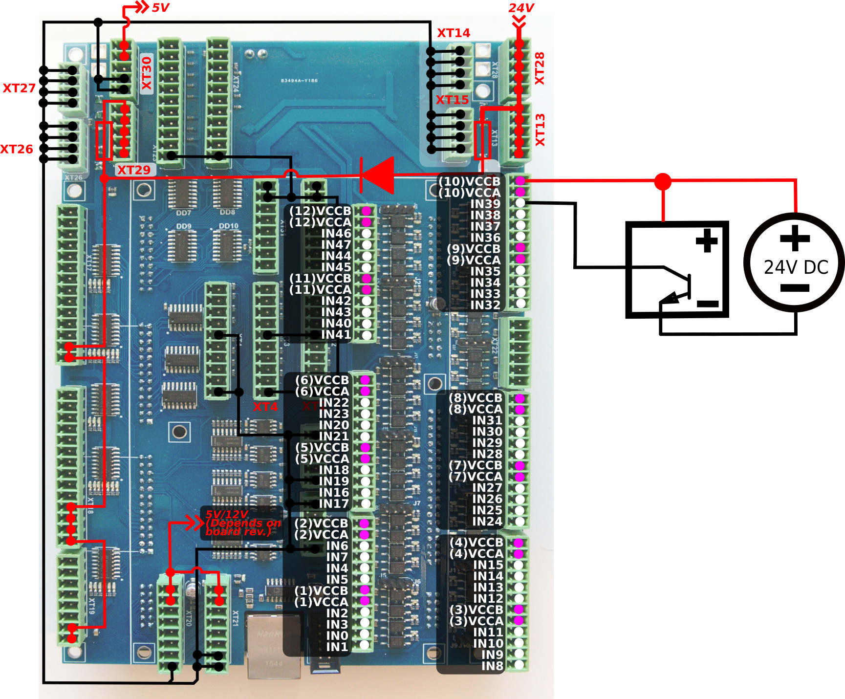
3-wire NPN sensor connection example
External power supply. Jumpers are open.
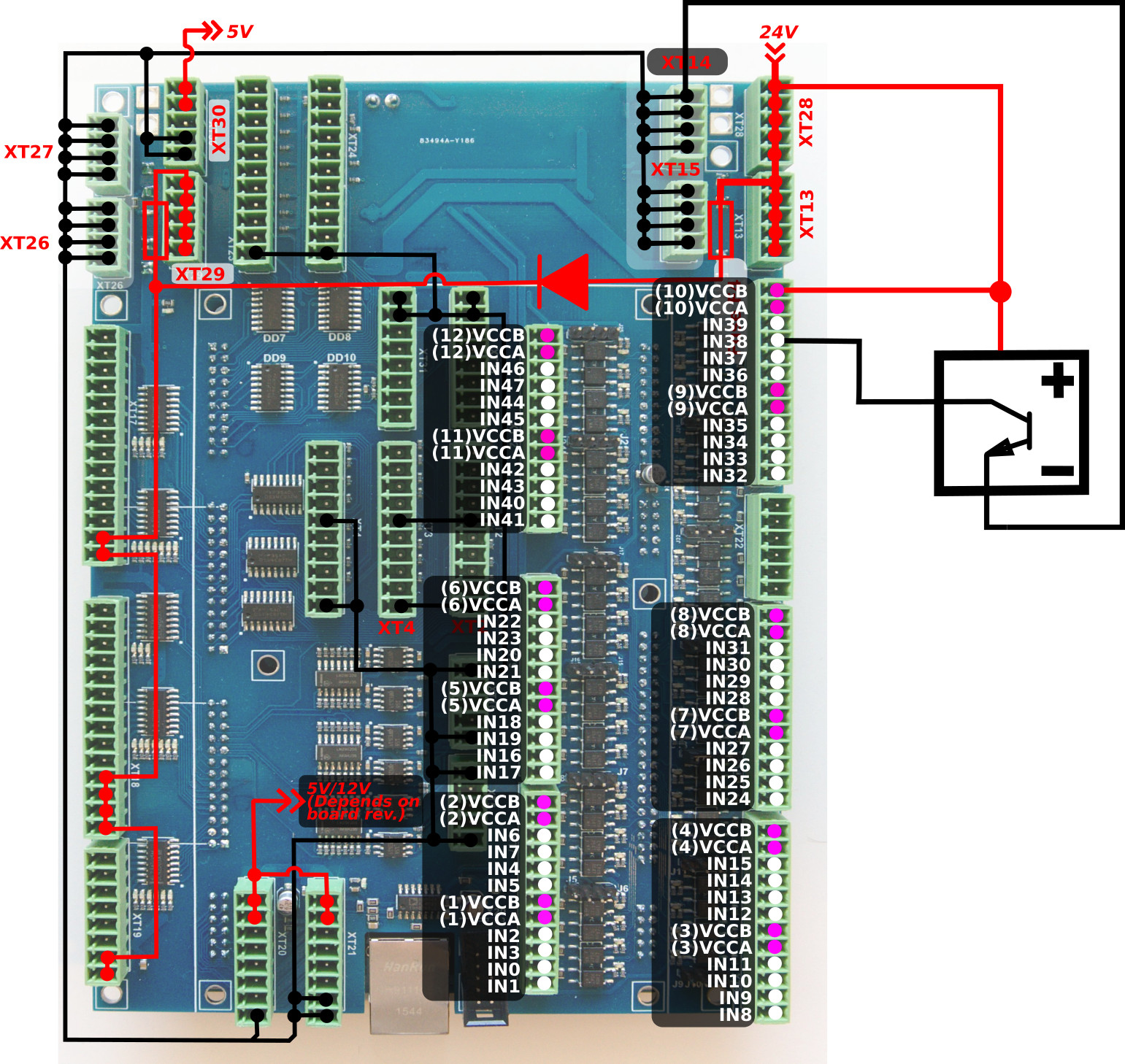
3-wire PNP sensor connection example
External power supply. Jumpers are open.
3-wire NPN sensor connection example (internal power supply)
Internal power supply. Jumpers are open.
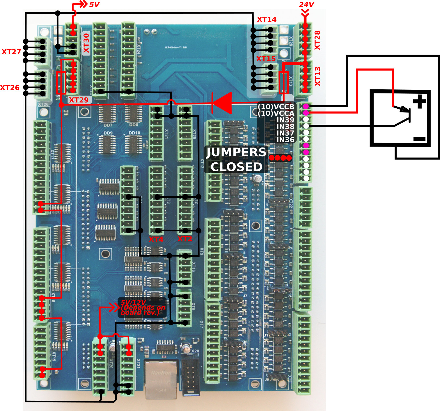
3-wire PNP sensor connection example (internal power supply)
Internal power supply. Jumpers are CLOSED.
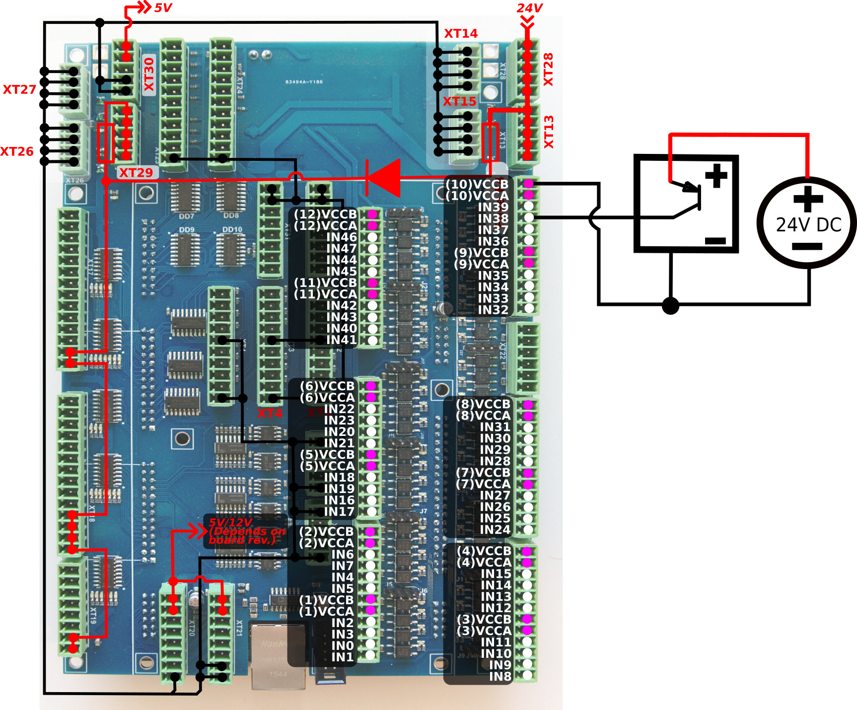
Switch connection example
-
Internal power supply
Jumpers for selected group are closed.
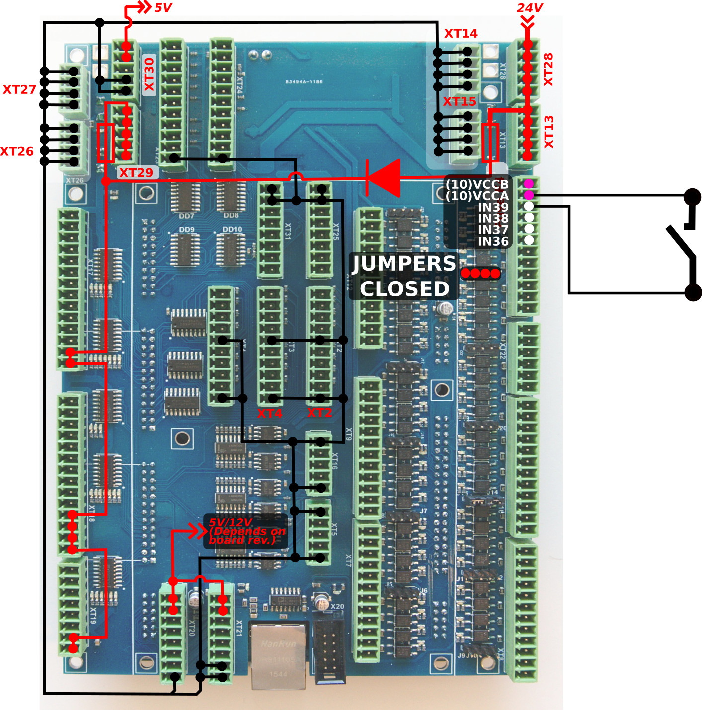
Common wire for 4 optocoupler units is connected to internal GND (0V) if the Jumper is closed. A switch should short another optocoupler input to +24V to activate input pin.
Jumper should be closed to connect the optocoupler pin to +24V. A switch should short wire to GND(0V). -
External power supply (#1)
JUMPERS ARE OPEN
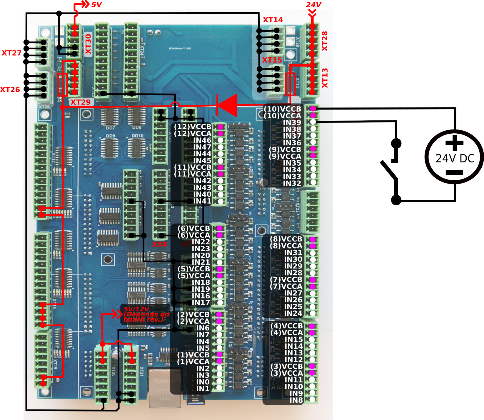
-
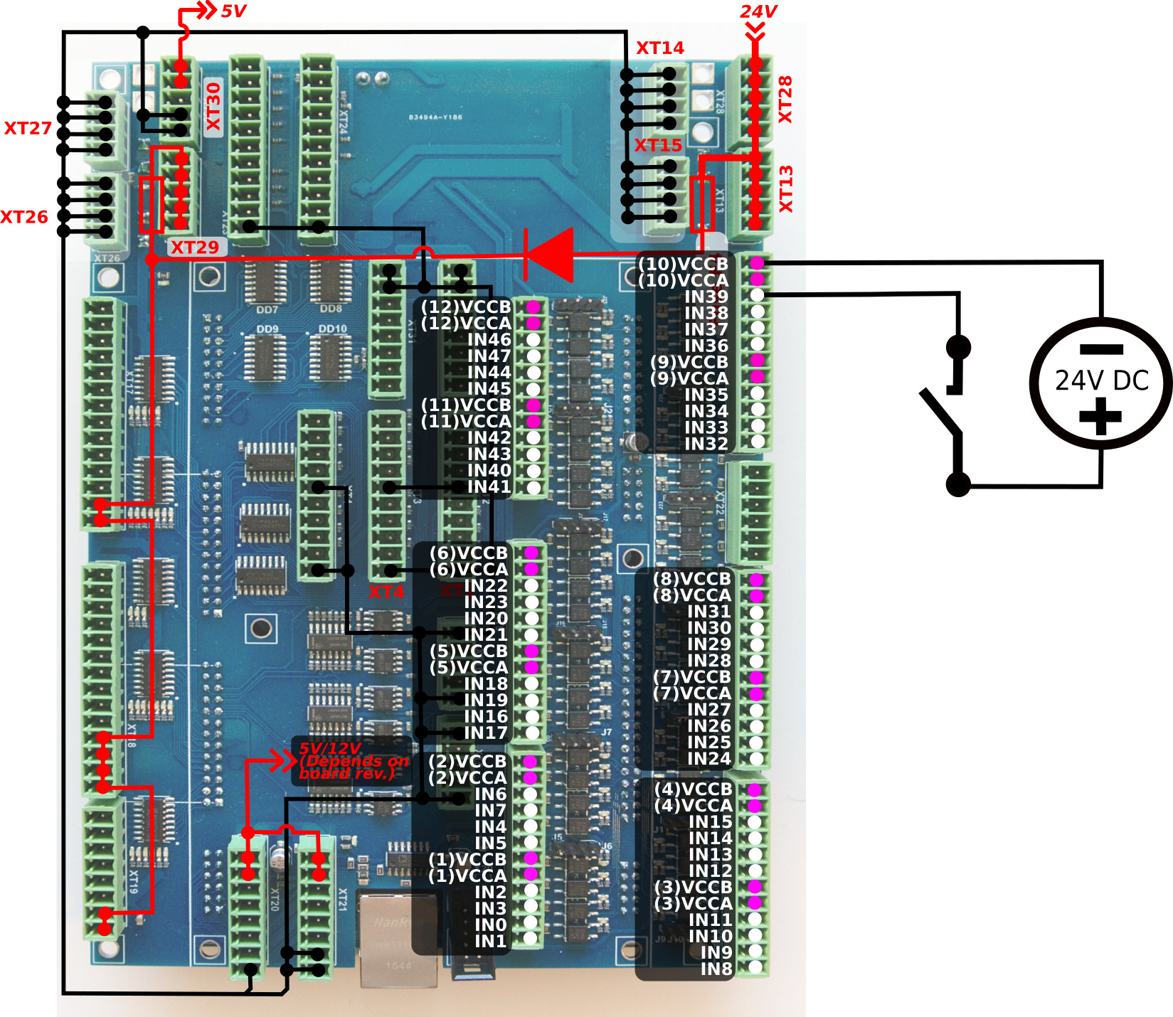
External power supply (#2)
JUMPERS ARE OPEN
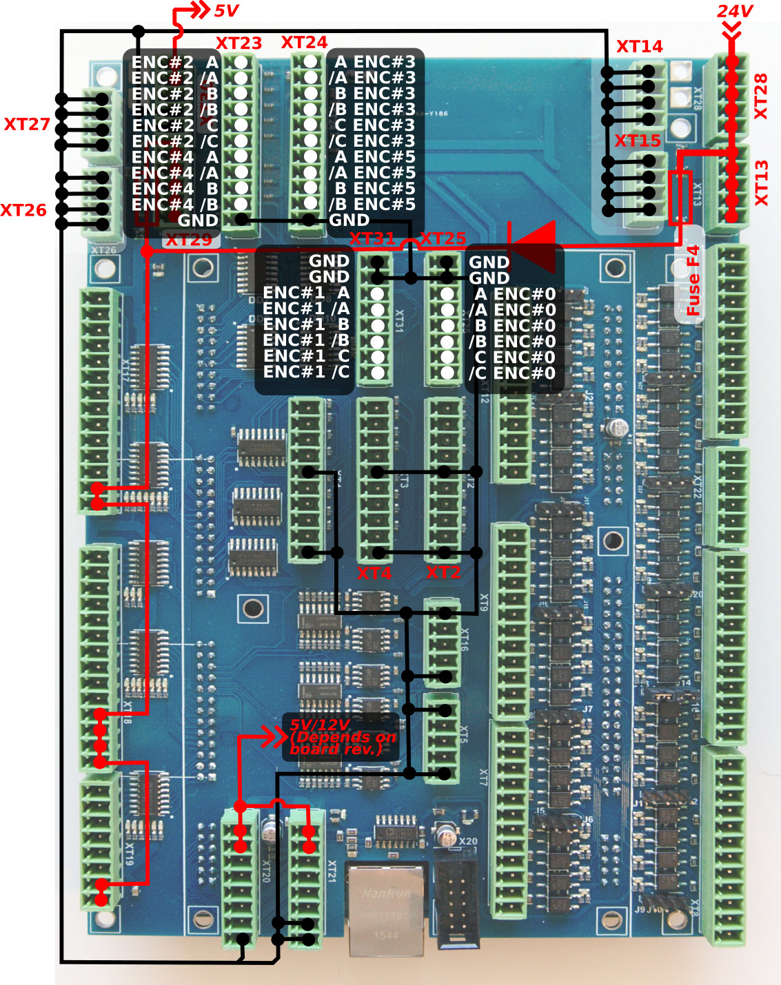
ET10 Encoder inputs
ET10 board has 6 Incremental encoder inputs. There are 4 complete ABC encoder inputs (A/B quadrature encoder signals and Z signal) and 2 reduced AB encoder inputs. ET10 encoder inputs conform to the RS422 standard and are compatible with most of the servo drivers and line driver incremental encoders. 34C86 chip is used in ET10 as a receiver for the encoder signals. Internal schematic for line driver encoder inputs is shown in the picture below.
INCREMENTAL ENCODER inputs schematic (1 Encoder, ABC signals are shown)

ENCODERS channels 0,1,2,3,4,5 pinout
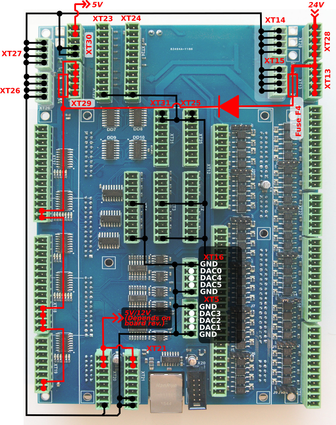
ET10 DAC +/-10V DAC outputs
ET10 control board contains 6 channel +/-10V DAC outputs. This outputs can be used for analogue servo drivers closed-loop control, spindle speed control or any other application that requires IN analogue signals in +/-10V range.
Connectors XT16 and XT5 are used to connect DAC outputs. The connectors pinout is shown in the picture below:
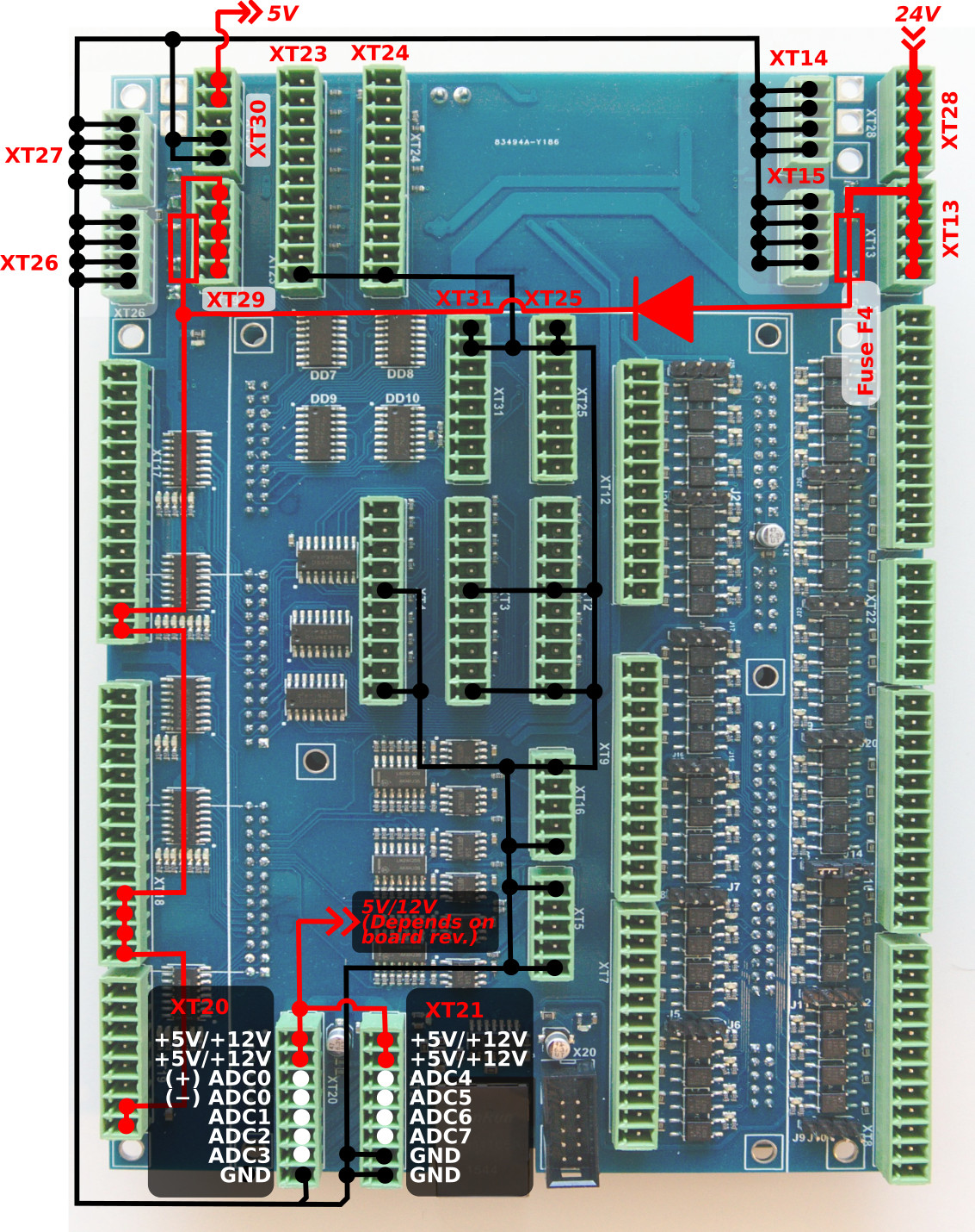
ADC Inputs
myCNC-ET10 Control board has 8 ADC inputs. ADC Channel #0 has differential amplifier input pins and suitable to connect differential analogue signals up to 30V range. The rest 7 of ADC inputs are in the 0 to 5V Range. ADC inputs connectors have also GND and +12V DC output pins for convenient potentiometer connection.
Input schematic of ET10 differential ADC input (Channel#0) is shown below. 
Input schematic for ET10 0-5V ADC inputs (Channels#1…#7)

Connectors XT20, XT21 are used to connect ADC inputs. The connector pinout is shown below
The picture below shows an example of a potentiometer connected to ADC2 input.

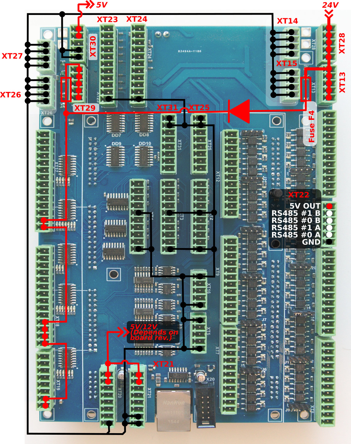
RS422/RS485 Bus
MyCNC-Et10 control board has a RS422/RS485 bus connector. Modbus ASCII/RTU and Hypertherm Serial communication interfaces are implemented in myCNC-ET10 control board. RS422 connector pinout is shown below:

Board dimension
myCNC-ET10 breakout board dimension
PDF: http://cnc42.com/downloads/et10bb-r9.pdf
DXF: http://cnc42.com/downloads/et10bb-r9.dxf
