CAD (3D)
The myCNC software includes an integrated 3D CAD module for designing tube and pipe cutting projects directly at the machine. This allows operators to create and modify pipe geometries, configure cutouts, and generate G-code without the need for external design software, streamlining the workflow.
(Note: While the CAD 3D and CAM 3D tools operate within the same intuitive software interface, this page focuses specifically on 3D design and part configuration. For toolpath generation, nesting, and machine motion setups, please visit our CAM 3D page.)
The CAD3D module provides an easy way to for the operator to design or import cut profiles for pipe/tube cutting workflows. The main features of the CAD3D functionality are as follows:
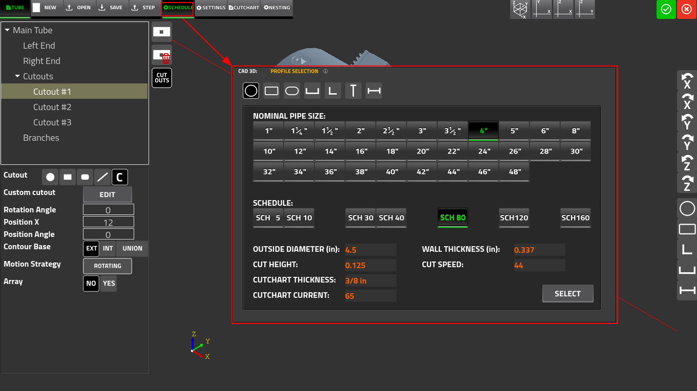
1. Profile Selection (Schedule)
The Schedule window is the primary entry point for defining the workpiece geometry for common supported profiles:
- Quickly select from standard cross-sections, including round tubes, rectangular tubes, C-beams, L-beams, and H/W-beams
- For structural steel, select standard W-sizes per AISC nomenclature (e.g., W4X13, W5X16, W6X12) from a scrollable list
- Selecting a size populates fields automatically, such as the overall depth of the section and the web thickness
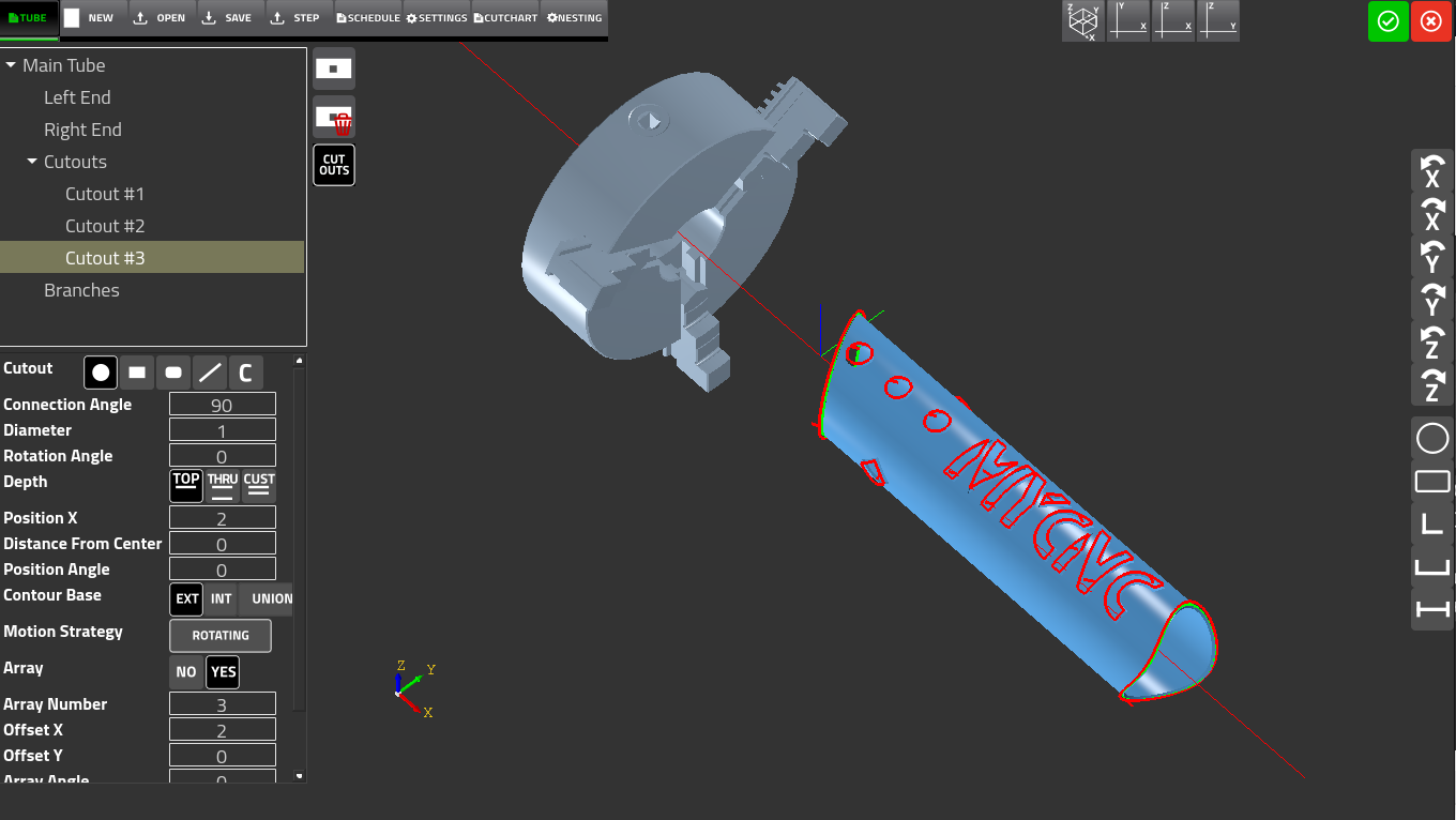
2. Defining Cut Features (Tube)
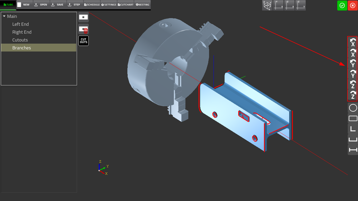
The Tube tab is the geometry editor for defining cut features on the workpiece. This interface is used to specify the end and cutout geometry for all commonly supported profiles, not just round pipes.
End Geometry:
- Easily specify the cut type, choosing from F, S or V45 cuts
- Define exact connection diameters, connection angles, and rotation angles to ensure perfectly mated parts
- Add weld preparation with a custom bevel angle directly to the part's end geometry
Cutouts & Holes:
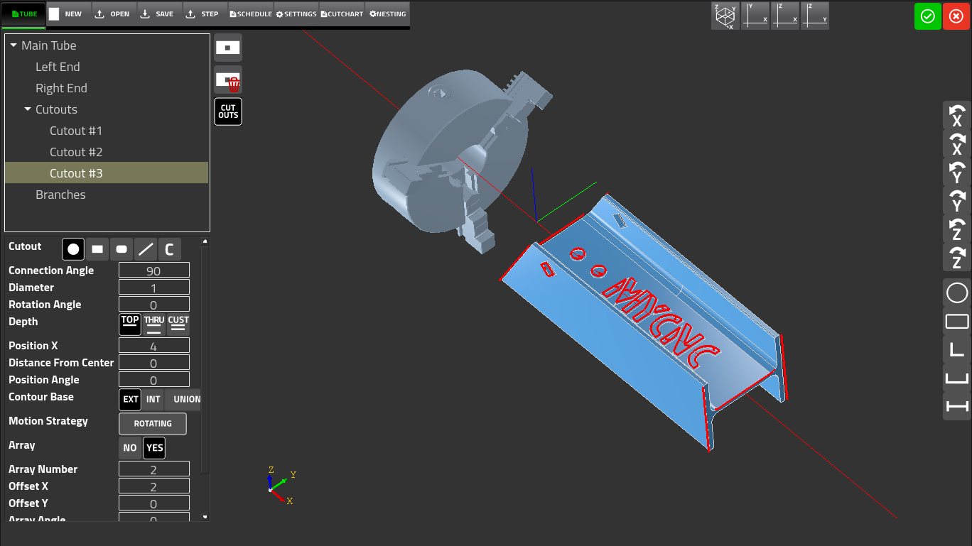
- Define holes or openings in the pipe wall using built-in shapes: round holes, rectangular holes, rounded rectangles, and lines
- For non-standard cutout geometry, use the Edit button to open the 2D CAD design module and draw custom shapes
- Maximize efficiency using the Array feature, which allows the user to duplicate cutouts without needing to design the same hole separate times
3. Custom Geometry (STEP Import)
For non-standard or custom structural profiles not available in the built-in schedule tables, myCNC allows you to import a STEP (.stp / .step) file
- The imported geometry replaces the schedule-defined cross section and renders immediately in the central 3D viewport
- Ensure your custom profiles are perfectly aligned with your machine's chuck using the X, Y, and Z-axis rotation buttons
- Each press applies a 90° rotation, and the 3D viewport updates immediately so the operator can visually confirm alignment before adding any cut features
Seamless Integration with CAM 3D features
Once your structural profiles are designed and your cut features are mapped out, the file is ready to transition to the manufacturing phase. While the CAD3D module dictates the geometry of what you are cutting, our CAM features determine how the machine executes it.
For detailed information on processing your 3D designs, please explore our CAM 3D Module features, which include:
- Contour Base Strategy: Choosing whether the contour dimensionality is based on the external or internal surface of the pipe
- Motion Strategy: Selecting between Rotating (using the A axis to rotate the pipe) or Non-Rotating (using lateral axis movement only)
- Settings & Cutcharts: Automatic integration of cutchart plate thickness, plasma current, cut speed, cut height, and kerf offsets
- Multi-Part Nesting: Arranging multiple copies of one or more parts on a single length of stock material, minimizing waste
For a demo of some of the features within the CAD3D module, please see the following video: