CAM (2D)
The built-in CAM module in the myCNC software allows the operator to transition from a digital drawing directly to production at the machine console. This reduces the dependency on external CAM software for day-to-day operations and improves workflow efficiency.
The following functionality is available within the CAM Editor:
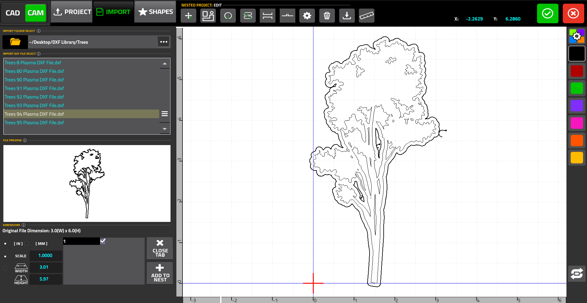
1. Control Program Import and CAD - There exist multiple ways of importing a control program into the myCNC software:
-
Import a DXF File or Project - The operator can import existing standard DXF drawings or load pre-saved proprietary project files.
-
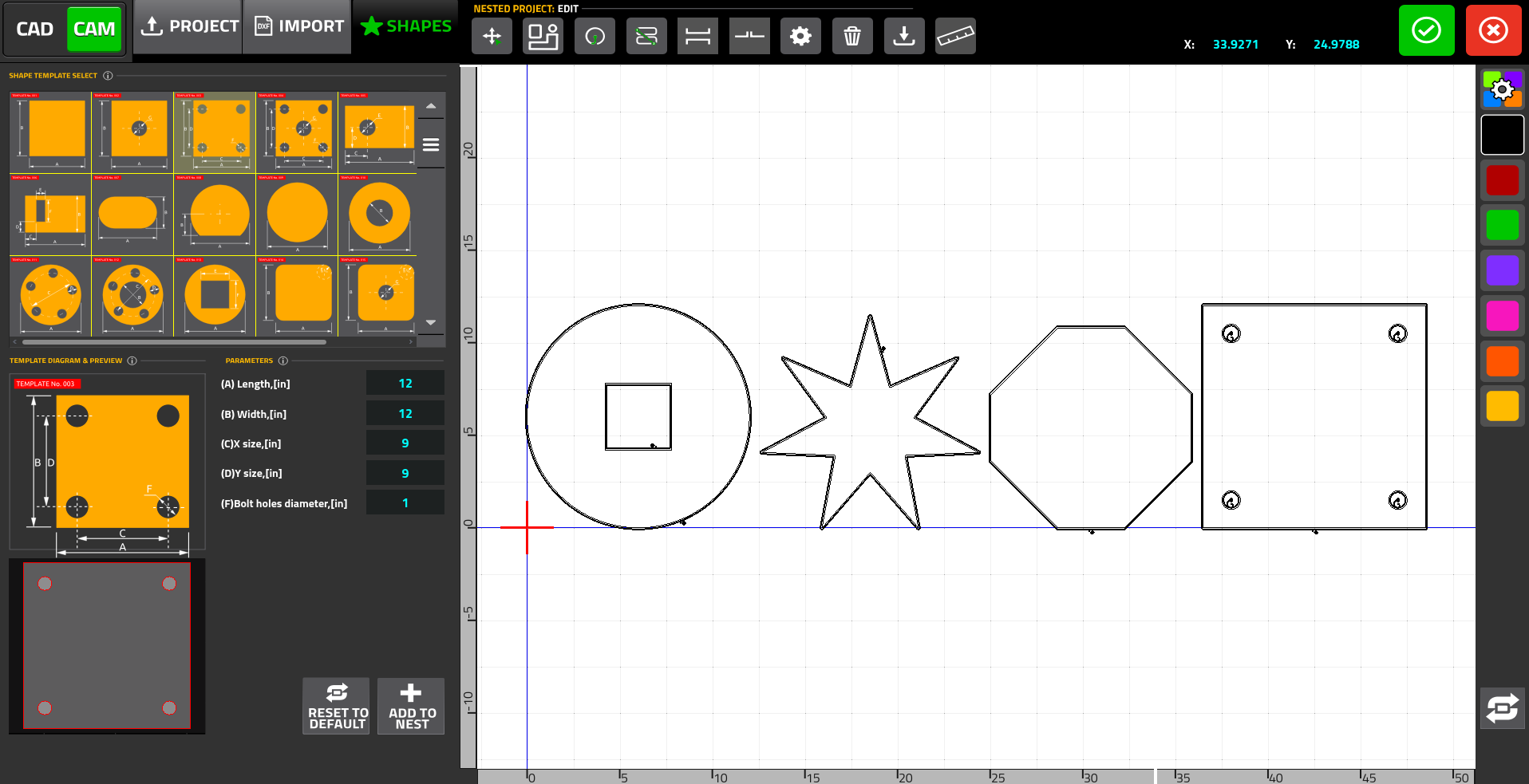
Shapes Library - The Shapes Library allows the user to pick a shape from a built-in parts library that features over 70 common shapes (such as rectangles, circles, and trapezoids), and to customize its dimensions:
-
CAD Editor - the CAD functionality allows the operator to draw custom shapes and figures from scratch, utilizing standard tools for lines and arcs. See the CAD page for more details.
-
Image (Alpha Version) - the Image functionality allows the user to import a standard
.pngimage into the software and generate a set of vectors that approximate the image based on a set of user-defined parameters, such as edge detection and filtration.
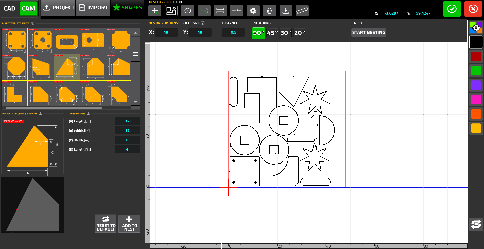
2. Editing the Imported Files & Nesting - once the files have been imported into the editor, the user can then manipulate and edit them further:
-
Part Selection and Nesting - parts can be easily moved, rotated, scaled, and mirrored. Additionally, the built-in nesting functionality automatically fits selected parts within a user-defined rectangular sheet size to minimize material waste. The operator can also specify the distance between parts and allowable rotation angles
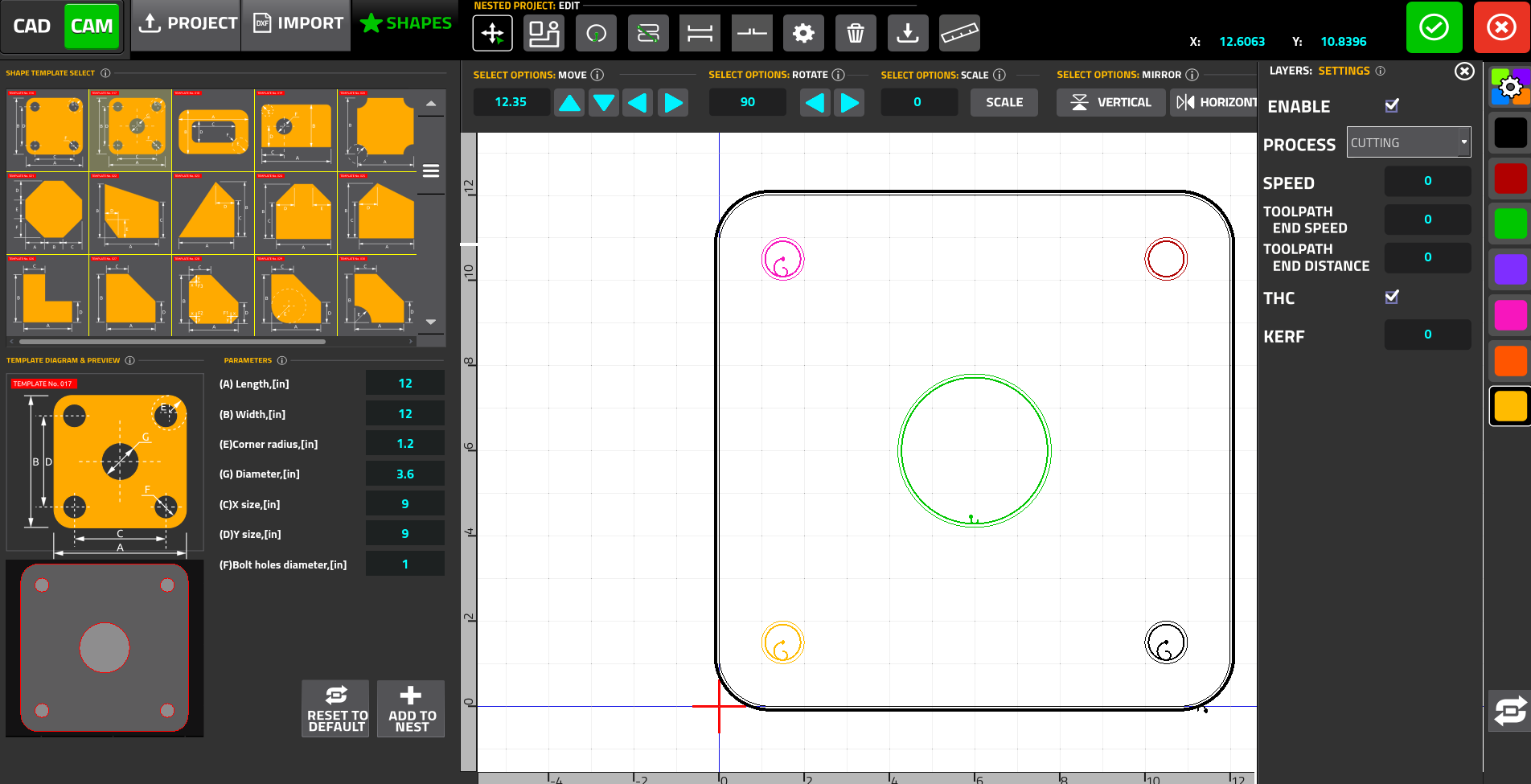
3. Cutting Parameters - the CAM Editor offers deep customization over the cutting process:
-
Leads Control - the user can manually reposition leads along a contour with a simple mouse click, or adjust their size. For small internal circular cutouts, the system applies a "Lead Center" strategy automatically.
-
Layers - DXF files can be separated into distinct layers, where each layer can be assigned unique processing parameters (cutting speeds, kerf compensation values, and Torch Height Control toggles).
-
Cutting Sequence - while the system automatically generates a generic toolpath sequence that prioritizes cutting inside contours before outside contours, the operator can manually override this to assign the exact sequential order part-by-part.
NOTE: For a complete breakdown of the CAM Editor UI and step-by-step instructions, please consult the full documentation at: https://docs.pv-automation.com/quickstart/mycnc-quick-start/cam-module