CAM (3D)
The myCNC software contains a number of 3D CAM features within its CAD3D module, allowing the operator to easily program the specifics of the cut based on the 3D design that is already loaded in the module.
(Note: While the CAM 3D and CAD 3D tools operate within the same intuitive software interface, this page focuses specifically on 3D CAM and cut configuration. For profile selection, loading in STEP files and defining the geometry of cutout features, please visit our CAD 3D page.)
1. Contour Base
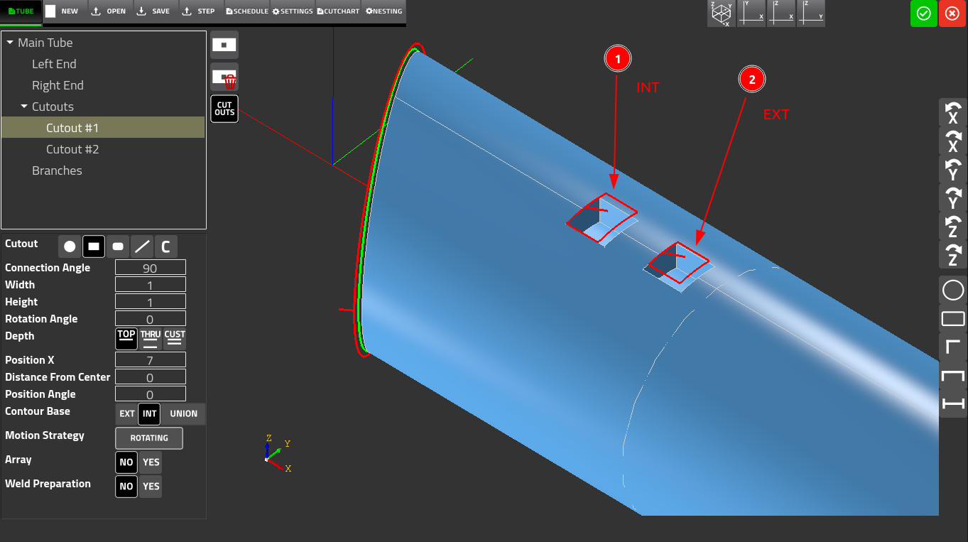
The Contour Base feature allows the user to specify whether an External or an Internal profile is to be used for a specific cutout's geometry. For instance, note that in the screenshot above, both cutouts are technically identical in size (1" by 1"). However, the difference between the two is due to the fact that they are using the two different surfaces (the external versus internal surface of the pipe) to calculate the dimensions of the cut path - due to the geometry of the plasma arc, the system will aim to maintain the exact proportions on one surface or the other.
2. Motion Strategy
Within the Cutout section, the Motion Strategy toggle is available (see screenshot above). The two options are:
- Rotating - uses the A axis to rotate the pipe as the hole is cut. This is the standard method and is suitable for most hole types and sizes.
- Non-Rotating - cuts the hole using lateral axis movement only, with no pipe rotation. This method is faster but is only suitable for smaller holes.
3. Nesting
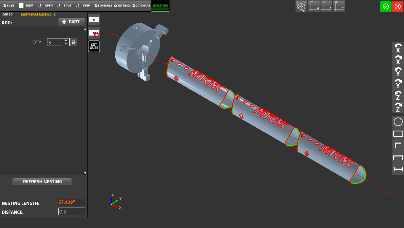
The Nesting tab allows multiple copies of one or more parts to be arranged sequentially on a single length of stock material, minimizing waste and setup time. The nesting workflow is as follows:
- Design the part geometry using the Tube and Schedule tabs or import a STEP file.
- Switch to the Nesting tab.
- Set the QTY (quantity) field to the number of copies required.
- Optionally press +PART to add a different part to the nest.
- Press REFRESH NESTING to recalculate the arrangement.
- Review the NESTING LENGTH and DISTANCE values to confirm stock utilization.
4. Automatic Kerf Compensation and Part Sequencing
The myCNC software automatically applies kerf compensation (compensation for the width of the cut) and positions the lead-ins at the pierce points. If multiple parts/cuts are present, the system will automatically calculate the optimal part sequencing.
5. Defining Project Settings
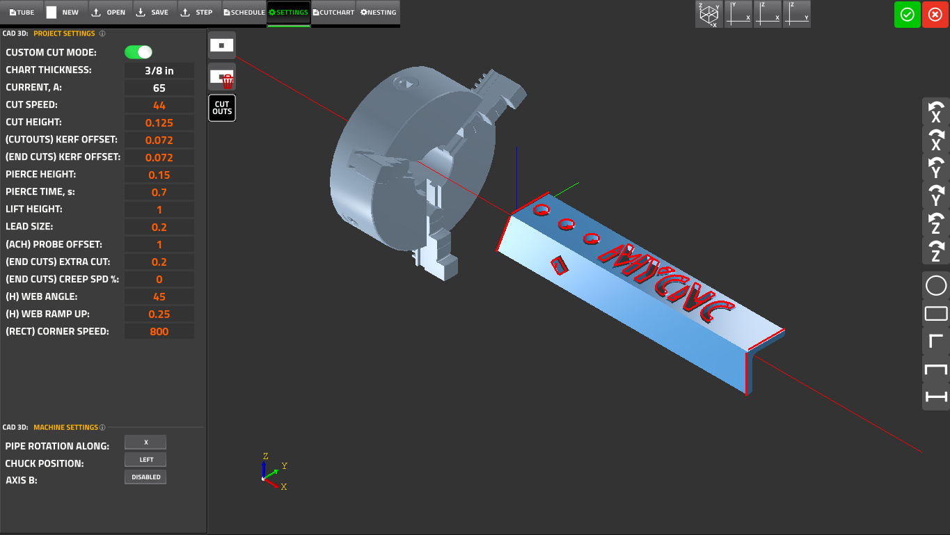
The Settings window allows the user to further define specific settings that are typically loaded automatically via the cutcharts for the selected plasma cutter unit.
The lower portion of the Settings panel contains machine-specific configuration:
- Pipe rotation along - Specifies the machine axis used for pipe rotation (X or Y axis).
- Chuck position - Defines which end of the tube is clamped (LEFT or RIGHT). This determines the reference origin for all programmed features.
- Axis B - special applications, allows to toggle whether the B axis (in addition to XYZA) is enabled.