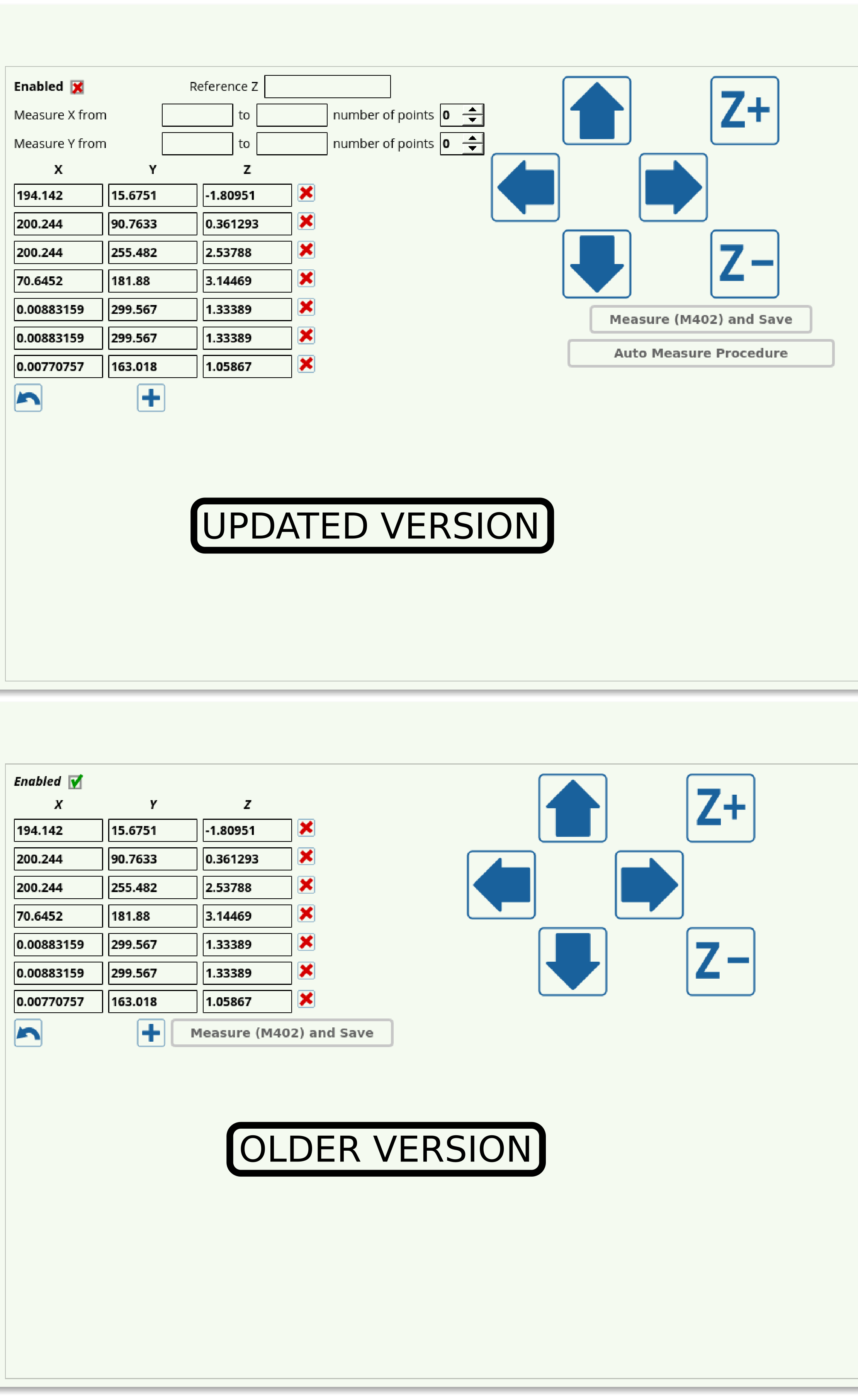
An automatic measurement procedure has been added to flatbed correction in myCNC software. Flatbed correction allows the user to account for the uneven portions of the working surface, by recording the surface z-coordinates over the entire working area or some part of it.
Previously, the process of selecting the points at which the height measurements would be taken was done manually, with the user moving the probe over the surface and lowering it down at each individual point which the software would then record. In the most recent myCNC version, this process has been automated. The user can now set the number of points that the machine must measure, and the coordinates of the area which the machine will be measuring, with the software automatically splitting that area into a number of zones to probe and record the surface height variations.
For more information on Flatbed Correction, please visit its Documentation page.
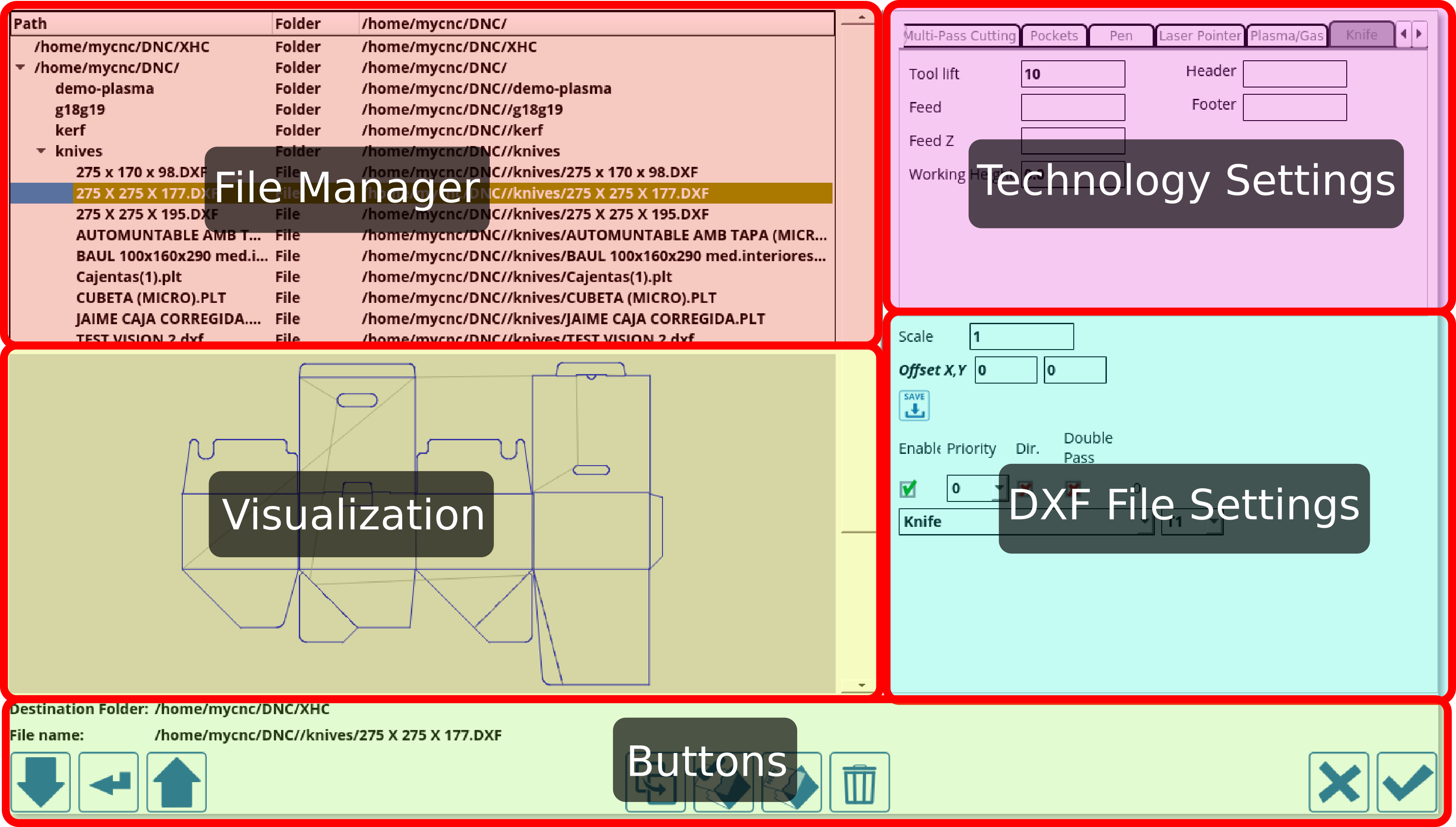
A new manual has been added to the myCNC Documentation site covering the basics of DXF import into myCNC software. DXF import allows the user to quickly design and draw a DXF file in a graphics/illustration software package such as Adobe Illustrator or Microsoft Visio, and then convert that DXF file into G-code upon importing it into myCNC software. The manual is designed to introduce the reader to the importing features and settings available to the user.
For more manuals, please consult the myCNC Documentation website.
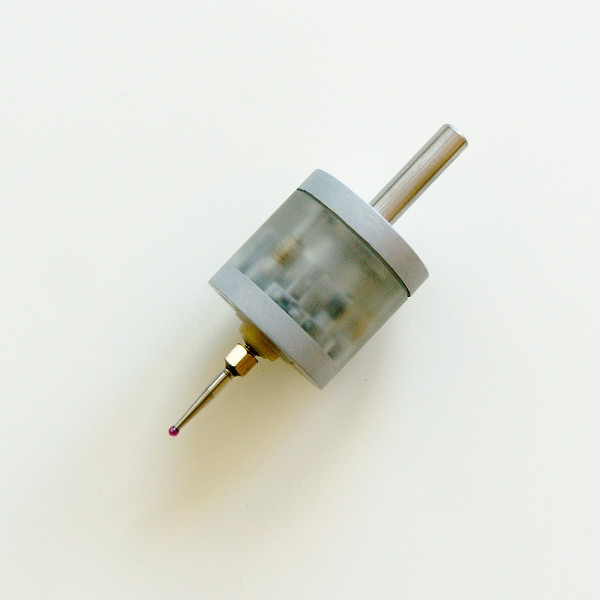
Probe Sensor tools have been added to the myCNC shop page. The probe tools can be used in a number of CNC applications in order to determine an exact position of the part that is located somewhere on the machine, or to determine the exact coordinates of the tool mounted on a CNC milling machine. The probe can find edges, corners, hole centers, and more.
The currently available CNC touch probe tools are the Wired Probe Sensor (SEN-PR-WR01), the Wireless Probe Sensor (SEN-PR-WL01), and the Wired Tool Setter (SEN-TS-WR01). The specifications and technical characteristics for each of these probe tools can be found on our Products page.
CNC Vision now features a fully automated calibration system, which allows the myCNC software to recognize reference markers and calibrate the camera in just a few clicks. In contrast with the previous calibration system, which required the user to manually calculate the proper pixel-to-length coefficients by moving the camera prior to use, the new system automatically moves and records the camera positions, allowing for a quick and easy setup process.

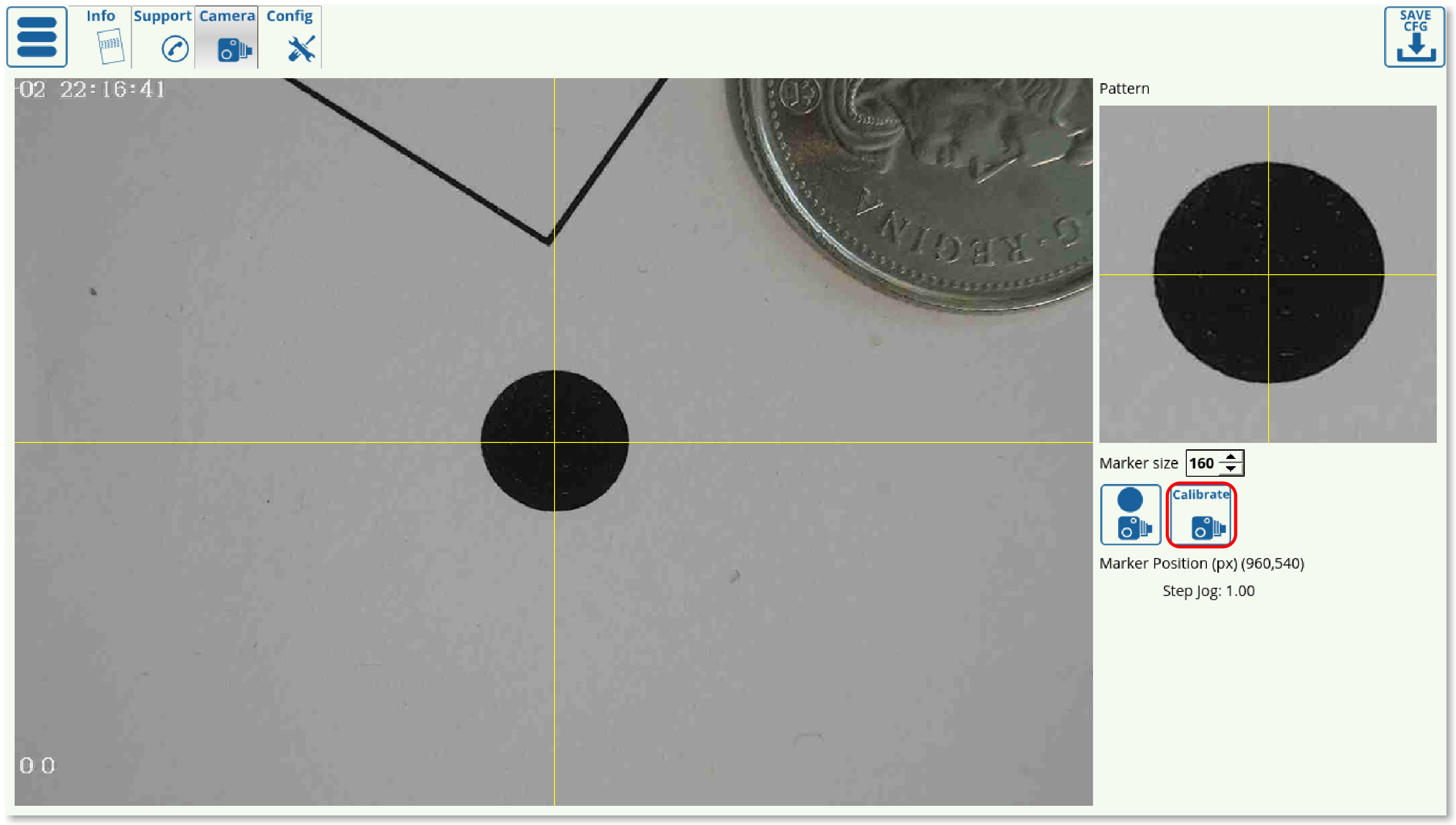
The new calibration features are available by downloading the newest myCNC software installation files from the Download page, or by updating your existing software.
myCNC software now allows for a fly cut in laser cutting/engraving when thin materials are involved. The laser is moved over the working material without stopping or braking the machine, but instead rapidly turning the laser on and off without having to split the cutting process into separate contours. This is done without sacrificing precision by synchronizing the cutting and movements commands on the fly, allowing for accurate positioning within a fraction of a second and drastic reduction of machining times.
Unlike many conventional systems which begin to lose precision as the machine speeds go over a few meters/minute mark, the myCNC FlyCut solution allows for precision cuts of up to 0.1 mm at working speeds of up to 100 meters/minute.
The fly-cut features can be accessed through programming the M64/M65 (turn exit ON and OFF) commands, as well as M164/M165 (pulse-width modulation) in your preferred CAM software.