![]()
The myCNC team is currently developing a solution for waterject systems, allowing to optimize the waterjet cutting process. A waterjet system has the jet of water trail slightly behind the machine when cutting is done at relatively high speeds - this creates issues at corners or whenever a sudden turn is performed, impacting the quality of the cut. Currently, the way to mitigate this is to lower the cutting speeds and acceleration values, resulting in a better cut at the cost of more time being spent per each part.
The myCNC solution will allow the user to still perform straight-line cutting at high speeds, while taking into account upcoming corners in the cutting path by preemptively slowing down to a fraction of the cutting speed within an adjustable distance from each corner or sharp turn. This will allow those of our customers using waterjet systems to save time without sacrificing cut quality.
Stay tuned for further updates.
Last month, we have shared our plans for implementing per-program Z-height mapping in this blog post as well as in this beta-tester manual on our documentation website. Since first sharing the news about this height mapping feature we have added a number of options to configure the mapping process, including variable probe speeds, settings for variable probe lift and an option to manually take a number of measurements at necessary points to create a custom point array. At this point, the height mapping feature has been realized on the X1366M, X1366M4 and X1366M6 mill profiles. Additionally, testing and further development is planned for the X1366V profile.
Height mapping is currently being tested by a number of our customers. One of them has shared a video of a successful mapping test:
This feature will continue to be tweaked and updated in the upcoming days and weeks. Stay tuned for a full release!
Below is a video shared by one of Puruvesi Automations's clients, showing the first stages of making a machine designed for gear cutting equipped with a myCNC-ET1 controller. The cutting process depends upon synchronizing the rotation of the spindle with the rotation of the gear which is being cut. This is done using an encoder connected to the ET1. The setup can later be expanded to include synchronization of more axes to allow for further process automation.
.be
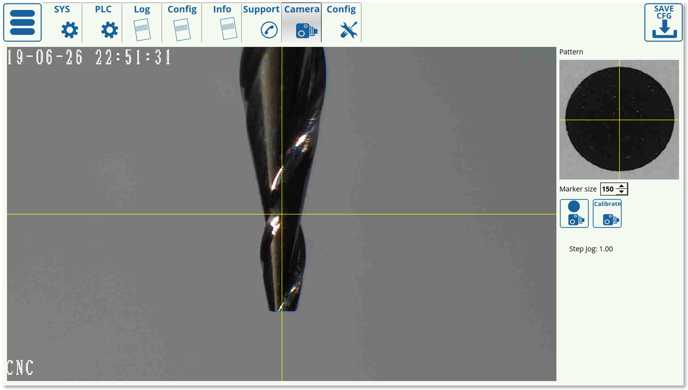
A process for tool calibration using a CNC Vision (camera) setup is currently under development. This procedure aims to calibrate extremely thin spindles (with spindle tip sizes on the order of 0.07-0.1 mm) without having to come into contact with a sensor, which can negatively impact the spindle to the point of breaking due to the sudden impact. Instead, the new calibration process will rely on a fixed camera, the position of which will be known in advance, which would then move the tool until its tip is perfectly aligned with the camera center.
The feature is currently in testing. Stay tuned for further updates.
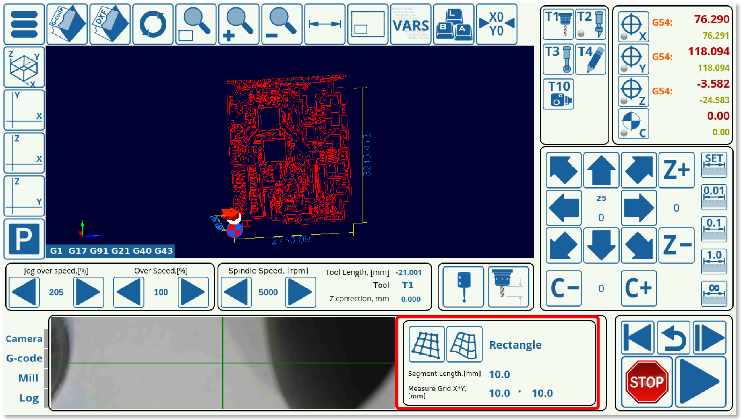
An alpha version of per-program height mapping has been added to the latest version of the 1366V profile, which can be used for PCB engraving/stone engraving in order to create a height map of each block of material loaded into the machine before beginning to run the program.
In order to utilize this, the user needs to load in a file which will be corrected, select the mode (rectangle/area), and then press the first button in the height mapping tab. This will create a grid for the probe to move over the material and to create a height map based on that grid. After probing has been complete, the second button is pressed, which adjusts the original program file to the height map.
It is possible to switch between a rectangle configuration, which will superimpose a rectangle on top of the program visualization and create a grid that covers that entire area, or, if the working zone is not close to rectangular in shape, the Area setting can be used to forego probing at the points where the engraving will not be taking place. Below is a visual comparison between the two modes:
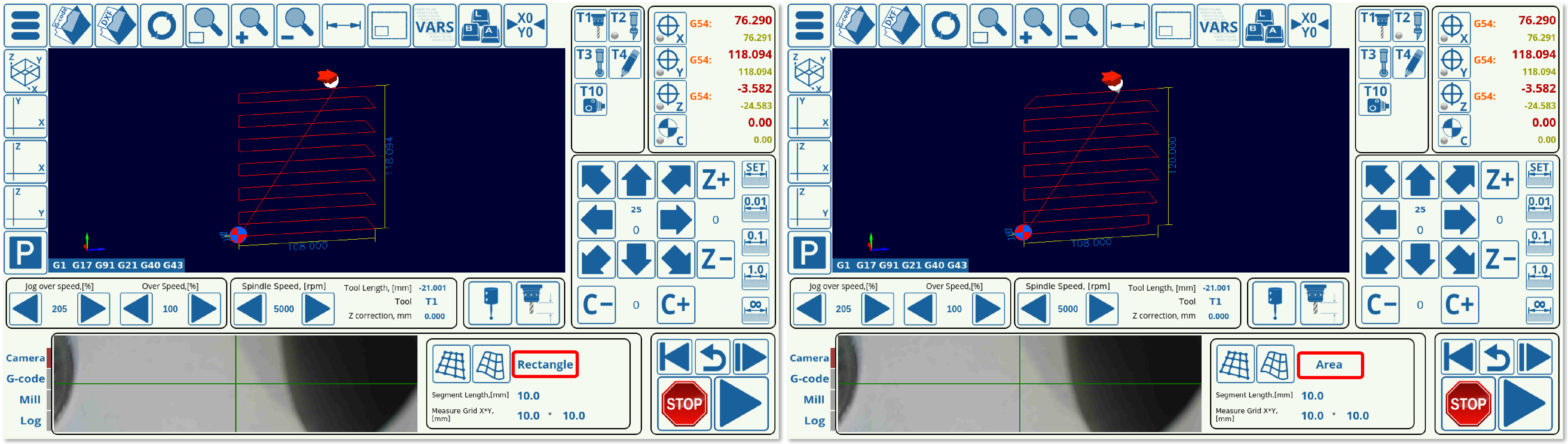
As can be seen, the Rectangle creates an orthogonal grid, while the Area mode disregards the parts of the rectangle that will not be used. Both of these modes have their advantages.
NOTE: This version of per-program height mapping is currently in its ALPHA stages. As such, not all features might be working as expected on all machines/configurations. Stay tuned for further updates.